This thread has been locked.

If you have a related question, please click the "Ask a related question" button in the top right corner. The newly created question will be automatically linked to this question.

UCC28070: 5KW Interleaved PFC input current distorted

Part Number: UCC28070

Tool/software:

Hi,

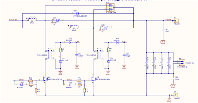
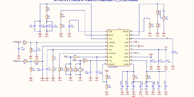
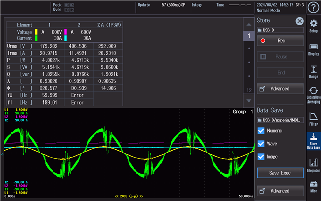
I'm testing a 5KW interleaved PFC using UCC28070, Vin=180AC, Vout=400DC, Fsw=60khz. 

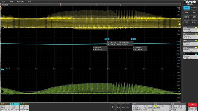
When I add the load current up to around 12A, the input current seems distorted, see below.

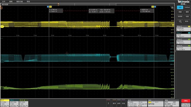
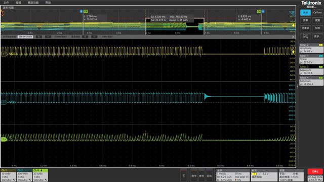
It seems it's caused by the unnormal controlling of PWM which makes the outline of the igbt current jagged and shutdown after that. 

Any idea where I should look into? Thanks!

  • Part of schematic:

  • Hello Tianwei, 

    Usually when the PWM switching suddenly stops and input current drops to zero, I suspect an overvoltage on the output triggered the OVP response.
    You do not display Vout, so I can't verify this suspicion.

    But an OVP shutdown does not explain the oscillation in the inductor current that precedes the shutdown each half-cycle.
    There seems to be some problem in the current loop.

    In your schematic, I see C53 and C54 (330pF each) on CSB and CSA signals.  I recommend to remove these two capacitors.    
    But they alone may not account for this oscillation.
    I also see the CT reset resistors R66 and R67 are 1k each.  This may not develop enough reset voltage for the CT when the current is high and the CSx signals may be corrupted.  I suggest to increase their values to 10kR each.  Check the higher reverse voltage on diodes D23 and D24.   

    Regards,
    Ulrich

  • Hi Ulrich,

    Thanks for the reply.

    I made the modification according to your suggestion and monitor the Vout. The oscillation in the inductor current remains. 

  • BTW this time I used a different IGBT, the current didn't shutdown, but still oscillation occurred.

  • Hello Tianwei,

    Thank you for the additional waveforms.  This shows that the switching shut down is not related to the current oscillations. 

    For the shutdown issue, I suggest to check the outputs of U11A and U12A.  I suspect that maybe the Input UVP may have triggered, but it is still possible to be from some other fault.   

    For the waveform oscillation, I wonder if the current amplifiers (CAOA and CAOB) are compensated properly. 
    Please use this calculator tool to compare what the tool recommends for compensation to your values:  https://www.ti.com/tool/download/SLUC114
    If your values are significantly different, please make appropriate adjustments.  

    Regards,
    Ulrich