TPS62840: Use as an inverting power supply

Part Number: TPS62840
Other Parts Discussed in Thread: TPS62480,

Tool/software:

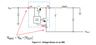
Hello, I found this reference: https://www.ti.com/lit/an/slva458b/slva458b.pdf?ts=1722951618887 that a buck regulator can be converted to a buck-boost and made into an inverting power supply. I'm wondering if the TPS62480 can be used in the same way, where the positive output is tied to ground with the chip ground tied to the negative output rail. 

I suspect the answer is no because of the additional zeros in the transfer function of the buck boost, but wondering if an engineer can comment on this or if anyone has done it before. I need the TPS62480 for its ultra low quiescent current but I also need a dual supply (+0.9V and -0.9V). 

  • Hi Jack,

    Thank you for using E2E,

    Inverting buck-boost is not something new and can be achieved by using TPS62840, but there are always some limitations. 

    If we use a normal buck converter as a inverting buck boost converter by using the below circuit there are certain criteria's to take care of, such as the the maximum input voltage(Vmax) of the device as it is limited by the maximum Vin (applied) and |Vout|, current stress and efficiency

     Please look into the application note to understand more about the inverted buck topology using a normal buck. Working with Inverting Buck-Boost Converters (Rev. B)

    Voltage stress: 

    Current Stress: Based upon the calculated peak and valley of the inductor current by using the below formulas we need to decide the maximum load current of the inverted buck. Since the peak and valley of the inductor current pass through the MOSFET power switches, they determine how much output current a given inverted buck can supply, when built from a normal buck. Simply Iout should be selected in such a way that Ipeak is lesser than the HS-FET current limit of TPS62840.

    Power losses and efficiency: Because of the larger voltage and current stresses in an inverted buck, when compared to the buck, the power loss of the inverted buck will be greater. This means that the efficiency of the inverted buck will be less than that of a buck under similar conditions. It is very difficult to estimate the efficiency before the inverted buck is designed and tested.

    Thank you & regards,

    Moheddin.

  • Moheddin, thank you for the information. I'm not concerned about device stresses because my max input voltage is 4.2V, my output voltage is -0.9V, and my nominal power output is 100uW, so there should be no issue with overloading the switches or inductor. I'm concerned about the TPS62840 having its own internal compensation, and that that compensation might not be sufficient to stabilize the converter if placed into a buck boost configuration. Additionally, the duty cycle equation is different in the buck boost than the buck, so I need to set the resistor on the VSET pin differently to achieve -0.9V. Can you comment on these two concerns?