This thread has been locked.

If you have a related question, please click the "Ask a related question" button in the top right corner. The newly created question will be automatically linked to this question.

BQ25618E: BQ25618E powered from Battery issue

Part Number: BQ25618E
Other Parts Discussed in Thread: LSF0108, SN74AVC8T245

Tool/software:

Hello,

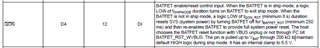
We have a new project with BQ25618E battery charger IC. In the prototype PCB board, BQ25618E is in default state without any configuration.

When USB connected, everything is OK, Vsys is about 4.14V, Battery can be charged. When the USB disconnected, Battery powering system still keeps OK. Vsys is about 3.89V when Battery is about 4V.

But the problem is, if the board has not been powered from USB and Battery for a while (for example, longer than 5 minutes), and then connect Battery only (powered from Battery), BQ25618E can't get Vsys output. 

Could you please help to find anything is wrong? How to solve this issue please?

Thanks!

  • Hello,

    What is the battery voltage when this is happening?

    Schematic seems ok.

    Regards,

    Mike Emanuel

  • Hello,

    Battery voltage is about 4.0V to 4.1V.

    Thanks!

    Mike

  • Hello,

    What is the actual BAT pin measurement?

    Regards,

    Mike Emanuel

  • Hello Micheal,

    It is 4.05V.

    Does it need anything control on QON pin?

    Thanks,

    Mike

  • Hi Mike,

    I do not believe that would cause the issue. Have you tried an ABA swap? In other words, put this unit on another board, and swap it with a known good unit on the other board.

    Regards,

    Mike Emanuel

  • Hi Mike,

    I have tested four prototype boards; and all are same.

    We tried connecting Vbat with Power instrument with 4.0V; and always can get Vsys output.

    But using Battery, sometime can get Vsys output and sometime not.

    One special condition is, when got Vsys output, disconnect Batttery, wait for about 5 seconds, connect Battery again, Vsys outptut all OK. But if wait for longer time, example, more than 2 minutes, connect Battery, Vsys can't get outptu.

    Don't know why?

    Thanks!

    Mike

  • Hi Mike, 

    Please see my comments below.

    But using Battery, sometime can get Vsys output and sometime not.

    One special condition is, when got Vsys output, disconnect Batttery, wait for about 5 seconds, connect Battery again, Vsys outptut all OK. But if wait for longer time, example, more than 2 minutes, connect Battery, Vsys can't get outptu.

    For case where you reconnect the battery after more than 2 minutes and cannot observe voltage at SYS have you verified voltage can be measured at BAT pin of BQ25618E IC? Additionally, can you test if battery will power SYS for this case after connecting then removing an adapter input at VBUS? 

    Your description that it always works with a power instrument in place of battery makes me wonder if a battery protection such as overcurrent or overdischarge is being tripped? 

    Best Regards,

    Garrett

  • Hi Mike,

    Finally I find it is caused by TI Level shift IC LSF0108DGSR. We put Vref-B direct to 3.3V; and datasheet shows after 200K Resister.

    This makes Vref-A (Vext from 4G module) dropped. and makes 4G module in an uncertain state and drawn lots of current when Power on from Battery, and makes BQ25618E going to over current protect state. 

    I manually make correct on Verf-B on LSF0108DGSR; Vsys output OK (powered from Battery) now.

    But the new question are:

    1. will LSF0108DGSR be damaged if we connect 3.3V direct to Vref-B?

    2. LSF0108DGSR is for 4G module & MCU level shift, will this damages 4G module or MCU?

    Thanks,

    Mike

  • Hi Mike, 

    Great to hear you found the cause and confirmed its related to overcurrent protection of BQ25618E. 

    I have assigned this thread to the team that supports LSF0108 IC to help answer your new questions. 

    Best Regards,

    Garrett

  • Hi Mike,

    For level shifting operation, it is suggested to have VREFB and EN shorted and then pulled up with 200kohm resistor to 3.3V.

    1. Yes, it is likely to damage the device with no 200kohm populated. There exists a leakage current sourcing from VREFB and sinking into VREFA side, that is limited by this resistor and can be found through VREFB- (VREFA+0.7V)/200kohm. 

    This Logic Minute Series helps to explain further in detail:www.ti.com/.../5614318177001

    Regards,

    Jack 

  • Hi Jack,

    We will connect VrefB to after 200K resistor. (VDD_EXT is 1.8V; 3V3_SF is 3.3V) 

    Another question, the signals are UARTs and I/Os, do we need adding pull-up Resistors for each signal? some signals are from A to B; and some are from B to A. 

    Thanks,

    Mike

  • Hi Mike,

    Yes, pull-ups are recommended for up translation.

    Note that UARTs are typically not open-drain. You may also see SN74AVC8T245 (push-pull) where pull-ups are not needed, thanks.

    Best Regards,

    Michael.