This thread has been locked.

If you have a related question, please click the "Ask a related question" button in the top right corner. The newly created question will be automatically linked to this question.

LM3488Q-Q1: One pc of 3488 show bad transient response time in start up

Part Number: LM3488Q-Q1
Other Parts Discussed in Thread: LM3488

Tool/software:

Hi expert,

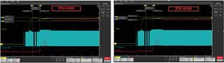
My customer found that there is one pc of LM3488 that has bad transient response:

The left is the bad one, the right is ABA swap with a new LM3488, the undershoot is beyond the UVLO point of the load.

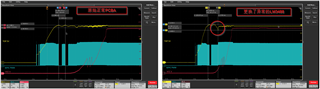
The left is a new PCB with good device and right is the new PCB with the bad LM3488, also show the big undershoot.

Do you know what may be the root cause, is it the quality issue?

Thanks!

  • Hi Jass,

    Thanks for using the e2e forum.
    I cannot say this is a quality issue just yet, as there are some marginal device variances from unit to unit which are still within the specified parameters of the datasheet.

    For this case, I would request a schematic and the parameters for Vin, Vout and load first.
    Based on this, we may be able to fix the problem on system level.

    Best regards,
    Niklas

  • Hi Niklas,

    Here is their schematic, the input is 15V, the output is 5V/1A. 

    They have tested many chips on the same board repeating 50 times for start-up, different LM3488 show different voltage drop as below. The normal one would be 4.8V like green curve, the bad one would be 4.5V like deep blue current, causing UVLO.

    Is there any thing to optimize for compensation network?

    Thanks!

  • Hi Jass,

    Thanks for supplying the schematic.

    If I understand correctly, the voltage drops happens on any device, but for the suspicious IC, the voltage drops is much larger, so it causes trouble with UVLO.
    The voltage drops happens because the load increases at this point of time?
    For this case, the issue might be solved if the general transient response is optimized for the design.

    The general schematic structure looks okay to me.
    Here are some point I would like to highlight:

    - They can consider using are more aggressive compensation network. This will make the device react faster to transient and reduce voltage drops.
    Unfortunately, we do not have a calculation tool for LM3488 SEPIC yet, so the ideal values need to be calculated by hand.
    Just for a quick lab test, they can increase Rcomp and reduce Ccomp, which should increase the bandwidth. They they can measure if the drop becomes better.

    - They only use one electrolytic cap of 100uF at the output. We generally recommend to add ceramic capacitors as well.
    These have lower ESR, which makes them faster and better for filter switching noise.
    For the next revision, I would recommend to add ceramic caps both at input and output. (e.g. two or three 2uF caps can have a notable improvement)

    - The gate resistor of 100 Ohm is rather large. If they switch node waveform looks stable in this design, this is fine, otherwise they can consider reducing the resistor to 10 or 30 Ohm to improve efficiency.

    Best regards,
    Niklas

  • Hi Niklas,

    Thank you for these suggestion! Can we add C12 for better transient? What value is better for this case?

  • Hi Jass,

    Adding a C12 cap will affect the loop regulation, but I would expect it to slow the compensation down, instead of increasing transient response speed.
    Attached is an application note on loop compensation design theory. LM3488 is a peak-current mode controller with transconductance error amplifier.
    /cfs-file/__key/communityserver-discussions-components-files/196/2627.slup340.pdf

    Best regards,
    Niklas