LM25037: Full Bridge Design Advice and Ideas

Part Number: LM25037
Other Parts Discussed in Thread: UCC28951, LM5045, UCC28251, UCC29002, UCC28C51, TL431

Tool/software:

Hello,

I'm building a 500W benchtop supply. I want it to be modular so that I can parallel it for high power. I've attached my initial set of specifications below. The output voltage down to 3V will be power derated, I'm still working out at which voltage I'll start derating.

Power flow: 2-stage EMI filter -> UCC28019ADR (PFC) -> Full bridge ( LM25037 - ?)

I was hoping you could help with the following:

  1. Is my Full bridge IC choice good given what I'm trying to do?
    1. I would have liked a 1.5A gate drive so that I can drive some toshiba fet's that I know work well and aren't overly expensive 
  2. To make this power supply modular and easy to parallel between N number of power supplies, what are some important characteristics that need to be taken care of for this to work smoothly?
  3. Any advice you think is pertinent please share.

Cheers 

  • Hi,

    1. For full bridge, you may consider UCC28251, LM5045, or UCC28951.

    2. For parallel capability, you may want to consider UCC29002 load sharing.

    3. see #2.

  • Hello,

    I don't want to do a phase-shifted FB, so that leaves UCC28251 or LM5045. Can you please explain why you would choose one over the other, pro's and con's given what I have shared and your own experience? Please provide more than 1 sentence.

    I don't have experience paralleling N amount of power supplies, FYI. When implementing current mode what signals need to be shared between power supplies? What are important characteristics that need to be taken into account? Do you need to take extra care with protection features such as overload or short-circuit? Does cycle-by-cycle current limiting need extra care when paralleling? Please explain each question in detail, not 1 sentence. 

    Is there a full bridge EVM for UCC28251?

  • Hi,

    LM25037 is for push-pull with on chip driver which would not be used since you use full bridge. If you use full bridge with external drivers then UCC28251 is better since it requires the external driver.

    LM5045 is for full bridge controller.

    So compared the three, UCC28251, LM5045, then LM25037 as the more relevant to your case or waste some thing.

    If you can design with LM25037 for full bridge it would be ok to design UCC28251. I do not have a reference design of UCC28251 full bridge.

    You can stay with LM25037 if you want.

  • Hong Huang,

    I'm not finding your answers to be very helpful outside of suggesting particular IC's which you did in the first comment. Can you please read my entire message and address each question. I see you somewhat addressed my first paragraph, but you ignored my entire set of questions in the second paragraph. 

    please address each question and provide clear recommendation(s).

    This should not be a race of how many customers you can reply too, but the quality of your reply per customer question set.

  • Hi,

    I suggest you use UCC29002 for paralleling. So I think I answered all your questions.

  • No, you have not.

    How do I get a different person from TI to address this thread?

  • Hi,

    Then repeat your question so we can know which one not.

    You can send a message to your local TI contact and get help from email support if you do not think the E2E solves your question.

  • By reading this thread you should be easily able to tell which questions have not been addressed, or, even which answers you gave in which I was not satisfied with the response. I'm not sure what to say to be honest, other than can you please get another TI guru to come help provide insight into my questions and this thread.

  • Hi,

    Just repeat your question which you think not since I think I answered all your questions. 

    Or contact to your TI local support so to make support through email.

    1. When implementing current mode control what signals need to be shared between power supplies when parelling?
    2. What are important characteristics that need to be taken into account when paralleling these 500W supplies?
      1. Can the input EMI filters interact with each other?
    3. Do you need to take extra care with protection features such as overload or short-circuit?
    4. Does cycle-by-cycle current limiting need extra care when paralleling? 
    5. Between UCC28251 or LM5045 using full bridge, which one is better suited for the following specs/notes:
      1. Vin - 410 Vrms (PFC Output voltage fed into FB)
        1. 15 Vpkpk max
      2. Vout - 400V to 3V
      3. 35kHz switching frequency 

    I live in Vancouver BC Canada, what is a local TI rep I can be in touch with?

  • Hi,

    1.

    I suggest UCC29002 for output current sharing. Please look at the UCC29002 datasheet to check which signals are needed for sharing. You cannot directly connect the 500W converters together on their outputs to achieve acceptable sharing.

    2.

    Again, look at UCC29002 datasheet to help. On the input EMI filter, you can do one for all if you want to make modular design then the same EMI filter would before one or for all. Each 500W converter needs its own input filter to decouple its operation from others - basically other converters can have reflected ripple to this converter so its own input filter try to filter out these reflected ripples. You may consider to use frequency synchronization to reduce different frequency ripple caused frequency beating.

    3.

    This is your decision. You need to decide a single converter in fault or a fault happening when several in parallel what are your protections you need in your application.

    4.

    With UCC29002 each converter operating by its own but during C-B-C if that converter cannot provide enough energy then that converter is like out of the paralleled operation.

    5.

    LM5045 cannot get that low frequency of 35kHz. So UCC28C51 or LM25037 should be used. But UCC28C51 in f-sync can only be min 42kHz. So it looks back to LM25037 which is only device can be used.

    You can call this below to find out. 

    Contact us | Technical support | TI.com

  • Hi Hong Huang,

    thank you for responding in a more detailed manner.

    If I reconsider using UCC28951 because I want ZVS to enhance efficiency, will I be able to get the desired output voltage of 400VDC to 3VDC? I have not implemented PSFB before.

  • Hi,

    I assume you place UCC28951 on the primary side then using an optocoupler to make feedback cross the isolation barrier and using something like TL431 to for control to regulate Vout = 3V, then ok. If different please describe so to help to find if ok.

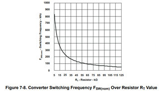
    A major concern is still 35kHz frequency. This device when designed < 100kHz the frequency change becomes flat and seems approaching 50kHz. If it is difficult to get 35kHz, it is better to decide if ok with > 50kHz.

  • Hello, 

    Yes that's what I had in mind for how to control the IC, placing it on the primary side like you mentioned. To clarify a couple of things and make sure we are on the same page:

    1. Did you understand my comment about Vout such that I want to be able to control the output voltage from 400VDC down to 3VDC?
      1. If so, would inserting pot into the TL431's resistive divider be a normal strategy?
    2. I think 50kHz should be fine, my idea there is to have a larger size magnetics but get a gain efficiency 
  • Hi

    1.

    You can use TL431 and normal - I do not see why you cannot use TL431 for 3V output voltage, you could add a secondary side winding for biasing as well. If you feel I do not get your point just to explain and ask again, it does not make much meaning to ask if I understand your point or not. I do not know what is your point unless you make explanation to me to help understanding. 

    2.

    Ok, as long as you are aware of the fsw limitation.

  • The reason I am now again checking if you understand my point is because you keep saying an output voltage of 3V, which is only 1 operating point I want to be able to regulate. I also want to regulate the output voltage which will span from 400V all the way down to 3V. I am NOT talking about an input voltage of 400V being bucked down to 3V. I am talking about a regulated output voltage from 400V to 3V. I want the TL431 to have a potentiometer in the resistive divider that feeds a voltage to the reference pin so that I can set the DC operating point, which I am planning to target to regulate the output voltage from 400V to 3V.   Slight smile...

  • Hi,

    I am still not sure what your point is. You can use a pot to set up the Vout based on the TL431. You can draw a simple circuit to show what you want to do. I think to use a pot to set up TL431 reference pin to obtain Vout = 3V is ok to do. 

    From 400V to 3V, on a full bridge, usually a transformer is used. I assume you use a transformer.