- Ask a related questionWhat is a related question?A related question is a question created from another question. When the related question is created, it will be automatically linked to the original question.
Tool/software:
Hello,
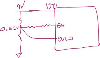
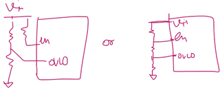
i am interested in the efuse TPS25961 device and would like to use it on 9v and 12v output power that i have. the rail switches between 9v and 12v by a switch so the efuse must tolerate up to 12v.
i do not require under or over voltage protection so i decided to hook EN pin directly to Vin, and VLO pin to ground. is this ok? should i put 100k series resistor or direct connections are ok?
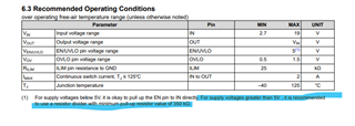
as for current limit i hoped to get it to work with 400mA or at least 350 mA but the resistor values lie in table 7.1 forbidden resistor values. I settled on 147k for 340mA but I hope to get it to 400mA, is that possible? how?
regards,