This thread has been locked.

If you have a related question, please click the "Ask a related question" button in the top right corner. The newly created question will be automatically linked to this question.

TPS65987D: dynamically switch source and sink in DRP mode.

Part Number: TPS65987D
Other Parts Discussed in Thread: TPS25751, TPS25730, TPS25751EVM

Tool/software:

looking for a simple solution to the following.

  1. A 2021 Apple iPad Mini 6 and that it has sink and source capabilities.
  2. I have the iPad and my device encased in a sealed housing.
  3. permanent USBC cable runs from iPad to my device to power my device
  4. a single USBC jack is exposed from the sealed unit which is only required to charge the iPad (no data connection required).

There are reasons to use an iPad instead of a battery pack that aren't relevant, but basically the iPad is acting as a battery that also needs to be recharged.

I am trying to assemble the device so that the iPad can both source and sink power automatically. I am not an USB expert and am really looking for a complete, simple, solution/example to copy. I would like it to be hardware configurable so that no i2c/programming/mcu is required.

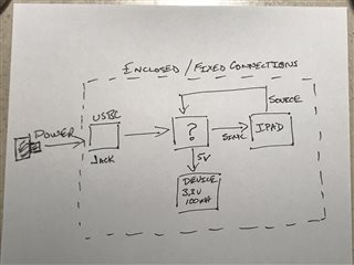
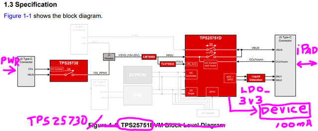
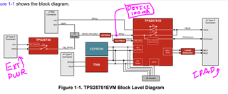
Block diagram of the concept. My device requires 5v ~100ma from the iPad. Power can be cut off to my device (or not) while charging if necessary.

  1. connect an exposed USBC permanently to the USBC on the iPad so that it can be charged
  2. permanently connect the iPad USBC to my custom pcb and treat the iPad as a power source
  3. when I plug the charger into the exposed USBC, I want the iPad to switch from being a power source to being the power sink
  4. that "?" is whatever I need to provide enough intelligence to tell the iPad to switch from source to sink (and sink to source when the power is removed)
  5. I don't need any data handling, D+/- isn't connected. Power only.
  6. I tried to solve this already by putting a 5K1 on CC1 and using a P-Channel to disconnect that in the hopes of having the iPad change roles, but that isn't working the way we need it to. It's not switching roles. I think we need a more sophisticated solution.

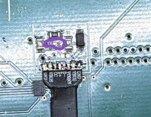
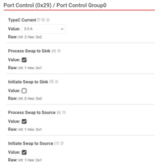
My problem is being able to dynamically change the iPad from sink to source. Currently I have been manipulating the resistor for testing, but I require the iPad to react solely on whether the charger is plugged or unplugged into the external USBC.

  • Hi Michael, 

    Thank you for reaching out!

    Based on your requirements, a DRP PD controller such as the TPS25751 would be a great fit

    Is my understanding below correct?

     I only see one USB-C Port in your block diagram, but from your description, it seems you may need two ports:

    • Port 1: Type-C input (sink) from USB-C Power Adapter to power the system. Essentially this could be used to power the PD controller.
      • The TPS25730 is a sink-only PD controller best suited for barrel-jack replacement applications.
    • Port 2: Type-C DRP (Source/Sink) connected via Type-C cable to the IPad's Type-C port
      • As a source, the PD controller would provide power to charge the IPad 
      • As a sink, the PD controller would request power (5V/100mA) from the IPad and use that power as an input to your Device 
      • The TPS25751 is a DRP PD controller best suited for power applications.

    The TPS25751EVM is a great reference featuring both the TPS25730 and TPS25751 devices (see block diagram below)

    Please let me know if you have additional questions/concerns. 

    Best Regards, 

    Aya Khedr

  • Thanks! I downloaded the configuration software. I will order an EVM board, but I can't find any PCB reference files for the TPS25730 and TPS25751. Are there PCB/Schematic files I can download and use with Altium?

    edit: TPS25751EVM is out of stock everywhere.

    Individual PCB reference files for the TPS25730 and TPS25751 that I can combine for my application would be really helpful. I see the schematic/pcb images in the TPS25751EVM pdf, but I would like something that I can just import into Altium if possible.

    Since I am not doing any data or battery charging, it looks like this is close to what I require (grayed areas not needed)?

  • Hi Michael, 

    A couple questions on the block diagram: 

    1- I see that the EEPROM block is greyed out. How do you plan on loading the configuration onto the TPS25751? Will there be an MCU in your design?

    2- Could you elaborate more on your device requirements (5V/100mA)? 

    • Is it being powered from the Ipad? or from the PD controller's LDO3v3?
    • What is this device?

    Please accept my friend request so that I can share Altium files with you offline. 

    Best Regards, 

    Aya Khedr

    1. I'm still figuring out the device works. If EEPROM is required and part of the reference design then I will just include it. 
    2. My device if fairly simple, but includes a 3v3, 100ma COB-LED and an ESP32 processor. That is the majority of the active components.
    3. My device requires 3v3, 100ma. I am open to whatever the best option is. I was thinking power would come from the 5v iPad, but if PD controller LDO3v3 is a better option then I would do that. My device must work while the ipad is in source mode, but if my device also worked while the iPad is charging that would be a bonus.
    4. This is our first venture into using USBC as a power source, so it's new to everyone here as to what are the options.
  • Hello,

    Thank you for your inquiry. TI US is closed for Christmas. Please expect delayed responses this week.

    Merry Christmas and Happy Holidays!

  • Hi Michael, 

    We do not recommend powering your device from the PD controller's LDO3V3. 

    I would recommend powering the device from the 5V rail or the 3.3V rail if you would like for it to be powered when sourcing and sinking. 

    If it only needs to be powered when the PD is sinking, then I would suggest using the PD controller's PPHV. 

    Best Regards, 

    Aya Khedr 

  • That sounds good.

    1. Is the 5v rail PP5V?
    2. Is P3V3 the 3v3 rail?
    3. "when sourcing and sinking" is great. If I can have both, no reason not to.
    4. I can't find the Altium files, but I'm not sure where to look? I accepted the friend request previously.
      Please accept my friend request so that I can share Altium files with you offline. 

      I'm guessing my TPS25751 configuration file would look like the following:

      Fullscreen
      1
      2
      3
      4
      5
      6
      7
      8
      9
      10
      11
      12
      13
      14
      15
      16
      17
      18
      19
      20
      21
      {
      "questionnaire": {
      "device": "TPS25751",
      "toolBuildVersion": "1.0.2",
      "answers": [
      null,
      1,
      4,
      0,
      0,
      0,
      3,
      0,
      0,
      1,
      1,
      null,
      0,
      0,
      0,
      0,
      XXXXXXXXXXXXXXXXXXXXXXXXXXXXXXXXXXXXXXXXXXXXXXXXXX

  • Hi Michael, 

    1. Yes PP5V is the 5V input to the device's internal power path (source only)
    2. Yes P3V3 is the 3V3 input to power the IC
    3. Great. My recommendation would be to ensure that the external DCDC's output voltage/current is sufficient to power your device and the PD controller. 
    4. Thank you for accepting the request, I will send them to you early next week. 
    5. In the configuration file provided, the source capabilities is set to a maximum of 100W. Do you require 100W sourcing to the Ipad? 
      1. The TPS25751D has a 5V/3A internal power path (max 15W standalone). If you require sourcing >15W, an external DCDC would be needed to generate higher voltage/current levels. 

    Best Regards, 

    Aya Khedr 

  • Yes PP5V is the 5V input to the device's internal power path (source only)

    will I also get a 5v sink from the ipad when the external usb is disconnected? The goal is to have uninterrupted 5v whether external usbc is connected or not.

    ensure that the external DCDC's output voltage/current is sufficient to power your device and the PD controller. 

    my device only requires 3v3 @150mA

    In the configuration file provided, the source capabilities is set to a maximum of 100W. Do you require 100W sourcing to the Ipad? 
    1. The TPS25751D has a 5V/3A internal power path (max 15W standalone). If you require sourcing >15W, an external DCDC would be needed to generate higher voltage/current levels. 

    I am targeting the ipad mini6. I believe charging requirements for the ipad mini6 is 5v/3A.

  • Hi Michael, 

    will I also get a 5v sink from the ipad when the external usb is disconnected? The goal is to have uninterrupted 5v whether external usbc is connected or not.

    The TPS25751 can sink in a "dead-battery" condition (i.e. when external USB-C is disconnected). In this condition, the device would be powered from VBUS (from the IPad). 

    Note that PP5V will not be enabled in a dead-battery condition. 

    Please let me know if you have additional questions/concerns. 

    Best Regards, 

    Aya Khedr

  • The TPS25751EVM appears to be back in stock. Please let me know when the reference files are available.

    For production it would be better not to have to flash each TPS25751. Since I am not using a TI battery charger, will I need to flash the TPS25751? If flashing required for "dual role" or is that the default?  

  • Hi Michael, 

    I sent the files to you over private message.

    The TPS25751 is shipped empty, and requires an external EEPROM or MCU to load the configuration to the PD controller. 

    The Application Customization Tool (GUI) is used to generate the binary file needed to properly configure the PD controller with the desired behavior you would like to achieve for your application. See the TPS25751EVM User's Guide for more information on how to use the GUI tool. 

    Please let me know if you have further questions/concerns.

  • First, thank you for your help with this. I've gotten more clarity as to what we require. We purchased a TPS25730, that was simple, and just ordered the TPS25751EVM. I've gone through all of the TPS25751EVM documentation. 

    I am confident the TPS25730/TPS25751 is the correct solution. Our requirements boil down to:

    1. We can't disconnect/connect the iPad USBC
    2. We need to iPad to Source power when not being charged
    3. We need the iPad to Sink power when TPS25730/USBC is plugged in
    4. We need to power the Device regardless of iPad state

    Hopefully this will give you a better description of what we need. It is mostly what we discussed, but a few points I need clarity on:

    1. the connection from the TPS25751 to the ipad is permanent. The iPad USB-C is completely encased in a closed housing.
    2. The only exposed USB-C is the USB-C connected to the TPS25730.
    3. We have no battery or charger, so always a dead-battery condition. 
    4. The device requires power at all times.
    5. We determined the iPad requires 20W to charge. Seems to need 9v while charging and 5v while maintaining a full charge.
    6. The device will always have it's own 3v3 LDO, so 5v-9v is acceptable.
    7. PP5V isn't enabled in a dead-battery condition while the iPad is sourcing. Is VBUS (or PPHV) always available to use for my Device? In a dead-battery condition, is either VBUS or PPHV available when iPad is in either Sinking or Sourcing mode to power to my device. Device needs power even while the ipad is charging. 
    8. TPS25751EVM requires 15v-20v. I assume that is an EVM only requirement and that we can use a 20W (original iPad 20W USB-C supply) in our final solution?
    9. can you check the revised config settings? 

    Salient points from Ti chat:

    1. ⁠I would recommend powering the device from the 5V rail or the 3.3V rail if you would like for it to be powered when sourcing and sinking. 
    2. ⁠Note that PP5V will not be enabled in a dead-battery condition. 
    3. ⁠The TPS25751 can sink in a "dead-battery" condition (i.e. when external USB-C is disconnected). In this condition, the device would be powered from VBUS (from the IPad). 
    4. ⁠ensure that the external DCDC's output voltage/current is sufficient to power your device and the PD controller
    5. ⁠The TPS25751D has a 5V/3A internal power path (max 15W standalone). If you require sourcing >15W, an external DCDC would be needed to generate higher voltage/current levels. I understand this to mean the iPad will only source 5v/3A. IF I am understanding that correctly, that is fine.

    Fullscreen
    1
    2
    3
    4
    5
    6
    7
    8
    9
    10
    11
    12
    13
    14
    15
    16
    17
    18
    19
    20
    21
    {
    "questionnaire": {
    "device": "TPS25751",
    "toolBuildVersion": "1.0.2",
    "answers": [
    null,
    1,
    1,
    0,
    1,
    0,
    3,
    0,
    1,
    1,
    1,
    null,
    0,
    0,
    0,
    0,
    XXXXXXXXXXXXXXXXXXXXXXXXXXXXXXXXXXXXXXXXXXXXXXXXXX

  • Hi Michael, 

    I will review and get back to you with feedback by Wednesday.

    Best Regards, 

    Aya Khedr

  • Looking forward to your reply... Here is our latest update.

    We can only get the iPad to switch role to Sinking by unplugging/plugging the iPad USBC (which is connected to J3 EVM board).

    We got the TPS25751EVM board today and we are fairly comfortable with how it is working out of the box. However, our main problem is that the iPad won't switch to sink mode when the 730 chip is powered (through J2 with the original ipad 27W GaN). However, once we get the iPad into Sinking mode (by manually unplugging/plugging the ipad), it will switch from Sinking to Sourcing upon removing the GaN on J2.

    Our primary requirement is that the iPad USBC is aways physically connected to the 751(J3). We can't physically unplug it.

    Because of the timelines involved, if we can't fix the role switching issue the project is either going to be canceled or we have to pivot to an internal battery solution very soon.

    We have not tried flashing the EVM yet and have only used the out of the box setup. Perhaps there is a flash setting to solve this problem, but I didn't want to proceed without your input

  • Hi Michael, 

    The power role preference of the TPS25751 is set in the GUI Tool in Port Control Register 0x29: 

    If the "Initiate Swap to Source" bit is enabled, the PD controller will automatically send a PR_Swap request to the IPad if it currently behaving as the Source. 

    Please ensure that the J1 jumper settings are correct for the EVM to be powered from J2:


    Please let me know if you have additional questions. 

    Best Regards, 

    Aya Khedr 

  • Thank You! I am feeling very close to a solution. I infer from your reply that the iPad should be able to swap between Sink and Source without the USBC being mechanically removed from the iPad.

    yes J1 is configured as shown, which I believe is how it was shipped

    The power role preference of the TPS25751 is set in the GUI Tool in Port Control Register 0x29: 
    If the "Initiate Swap to Source" bit is enabled, the PD controller will automatically send a PR_Swap request to the IPad if it currently behaving as the Source. 

    This sounds good. With the GUI Tool, what question sets Port Control Register 0x29? Do I have my settings correct for what I am trying to accomplish? I added notes in the file to document my understanding of the settings... I am especially unsure as to how to answer #4, and if #4 affects BIT_7 of the 0x29 register...

    BIT_7 Initiate Swap to Source R/W 0h Configure PR_Swap to source initiation. If this bit is asserted, the PD Controller automatically initiates and sends PR_Swap requests to the Port Partner when appropriate if presently operating as Sink (C/P).

    Fullscreen
    1
    2
    3
    4
    5
    6
    7
    8
    9
    10
    11
    12
    13
    14
    15
    16
    17
    18
    19
    20
    21
    {
    "questionnaire": {
    "device": "TPS25751",
    "toolBuildVersion": "1.0.2",
    "answers": [
    null,
    1, // #1 Are you a power source and power sink? TPS25751 EVM
    1, // #2 27W(9v) - max to ipad for charging
    0, // #3 15W(5v) - max to our device
    1, // #4 What is the preferred power role 0=power source, 1=power sink
    0, // #5 no USB
    3, // #6 host & device - N/A
    0, // #7 suport BC 1.2, no
    1, // #8 liquid detection, no
    1, // #9 Vendor ID, no
    1, // #10 Product ID, no
    null,
    0,
    0,
    0,
    0,
    XXXXXXXXXXXXXXXXXXXXXXXXXXXXXXXXXXXXXXXXXXXXXXXXXX

  • Ok... I didn't realize the screenshot you provided was from the Advanced Configuration option toggle... When I selected Advanced Configuration I see when I can change Bit7 of 0x29... I set up my config as shown above and then I went to Advanced Config and set Bit7 of 0x29... It created a much more detailed config file.

    Does that sound like I followed the correct procedure? I can't get access to flash the board until Monday, but because of the timeline I am trying to get as much info straight as possible.

    Can you confirm the config file looks correct?

    Fullscreen
    1
    2
    3
    4
    5
    6
    7
    8
    9
    10
    11
    12
    13
    14
    15
    16
    17
    18
    19
    20
    21
    {
    "questionnaire": {
    "device": "TPS25751",
    "toolBuildVersion": "1.0.2",
    "answers": [
    null,
    1,
    1,
    0,
    1,
    0,
    3,
    0,
    1,
    1,
    1,
    null,
    0,
    0,
    0,
    0,
    XXXXXXXXXXXXXXXXXXXXXXXXXXXXXXXXXXXXXXXXXXXXXXXXXX

  • Hi Michael, 

    My apologies for not clarifying. Yes, the "Advanced Configuration" Mode provides the register view allowing for more configurability of the PD controller. 

    Some comments on the config file provided: 

    1- I see that you have selected a maximum sourcing power of 27W. The TPS25751EVM alone can source up to 5V/3A and would need to be paired with a battery charger to source >15W. 

    2- My understanding is that the preffered power role is Source (i.e. to charge the IPad). In that case, "Power source (provider)" should be selected in question 4. This will update the content of the Port Control Register 0x29 (configurable in Advanced Mode) to have "Process Swap to Source" , "process Swap to Sink" and "Initiate Swap to Source" enabled . "Initiate Swap to Sink" should be disabled. Essentially only one power role can be selected here. Upon connection, the EVM and Ipad will start the PD negotiation process in which the EVM will send a power role swap request to the Ipad to become the Source if it started as a Sink. 

    Are there any scenarios where the TPS would need to sink from the Ipad in a non dead-battery state? 

    Please let me know how testing goes on Monday. 

    Best Regards, 

    Aya Khedr

  • 1- I see that you have selected a maximum sourcing power of 27W. The TPS25751EVM alone can source up to 5V/3A and would need to be paired with a battery charger to source >15W. 

    The original iPad charger is 27W. If that is insufficient when have bigger ones that should be delivered on Monday.

    My understanding is that the preffered power role is Source (i.e. to charge the IPad). In that case, "Power source (provider)" should be selected in question 4. This will update the content of the Port Control Register 0x29 (configurable in Advanced Mode) to have "Process Swap to Source" , "process Swap to Sink" and "Initiate Swap to Source" enabled . "Initiate Swap to Sink" should be disabled. Essentially only one power role can be selected here. Upon connection, the EVM and Ipad will start the PD negotiation process in which the EVM will send a power role swap request to the Ipad to become the Source if it started as a Sink. 

    I set the configs in the Questionnaire as you said, including "Power source (provider)", and then double checked 0x29 with the Advanced Configuration and everything was exactly as you said... I copied the JSON below. 

    Are there any scenarios where the TPS would need to sink from the Ipad in a non dead-battery state? 

    No. Our whole goal with this is to utilize the iPad as the battery. There will be no battery or charger in the EE.

    If you have a tip regarding a scenario with a non-dead battery, please feel free to let me know. We will use this chipset in the future for other clients.

    Please let me know how testing goes on Monday. 

    Thanks again! I will definitely let you know! Super excited about getting this to work. The tech has implications beyond this one client.

    Fullscreen
    1
    2
    3
    4
    5
    6
    7
    8
    9
    10
    11
    12
    13
    14
    15
    16
    17
    18
    19
    20
    21
    {
    "questionnaire": {
    "device": "TPS25751",
    "toolBuildVersion": "1.0.2",
    "answers": [
    null,
    1,
    1,
    0,
    0,
    0,
    3,
    0,
    1,
    1,
    1,
    null,
    0,
    0,
    0,
    0,
    XXXXXXXXXXXXXXXXXXXXXXXXXXXXXXXXXXXXXXXXXXXXXXXXXX

  • Hi Michael,

    TI U.S. is on Holiday today. Please allow for some delay in responses. 

    Best Regards, 

    Aya Khedr 

  • Our understanding of how the 751 is supposed to work.

    1. w/o power on VSYS the 751 is a sink only device. - (this checks out, and is what we need)
    2. Flash the 751 with "#4 Power source (provider) sets bit7, unsets bit5, When power is supplied to VSYS (through J2 - TPS25730) the 751 should change from a Sink-only device to Source... We are guessing that the 751 is switching from Sink to Source, but the iPad is already in Source mode, so the iPad can't (or doesn't know to) switch to Sink mode??? We are not sure how to get the ipad to stop Sourcing and start Sinking without unplugging it.

    Goals/Restrictions:

    1. iPad to sink if a GaN is connected.
    2. iPad to source if GaN is not connected.
    3. iPad cannot be manually disconnected from the 751.
    4. PPHV is connected to the load, but the load can be mechanically switched (SPST) on/off.

    Currently

    1. After flashing to the 751EVM, the iPad oscillates between sinking and sourcing about every 1sec. PPHV also oscillates at the same rate.
    2. Gan disconnected from above, meter registers a constant 5v (iPad sourcing, as desired)
    3. plug GaN back into J2/TPS25730, meter continues to read 5v on PPHV. iPad does not charge or seem to acknowledge GaN and/or switch to Sink mode... 

    We feel like we have a good understanding of how the TPS25751D/TPS25730 should work and what we want, but we are either missing something or the chipset simply won't do what we want. Is there anything else we can try? And/or is there a faster level of support to get this to work? We would be willing to contract with a consultant to walk us through the solution.

  • Hi Michael, 

    1. 

    w/o power on VSYS the 751 is a sink only device. - (this checks out, and is what we need)

    That is correct. Without power on VSYS, VIN_3V3 is unavailable and essentially the device behaves in a dead-battery condition, in which it could be powered from VBUS.

    2. 

    Flash the 751 with "#4 Power source (provider) sets bit7, unsets bit5, When power is supplied to VSYS (through J2 - TPS25730) the 751 should change from a Sink-only device to Source... We are guessing that the 751 is switching from Sink to Source, but the iPad is already in Source mode, so the iPad can't (or doesn't know to) switch to Sink mode??? We are not sure how to get the ipad to stop Sourcing and start Sinking without unplugging it.

    In this case, are you initially powering the EVM from VBUS and then supplying power to VSYS? If that is the case, then the TPS25751 is still in a dead-battery condition and this flag would need to be cleared via MCU intervention via a 4CC command. The Boot Flags register 2Dh has a "Dead Battery Flag" indicator.


    For testing purposes, I suggest powering on the EVM first and then connecting the Ipad to see it behave in a non dead-battery condition. When initially powered from VSYS, the TPS25751 should be sourcing to the Ipad (because of its power preference setting in which it will send a power role swap to the Ipad)

    The goals mentioned is achievable with the devices being discussed here. It does look like you will need an MCU/EC in your system to clear the dead-battery flag and to send power role swap commands to the device when needed. 

    Do you have a PD analyzer? PD logs will provide valuable information on the PD negotiation between both devices, EVM and Ipad and will help us understand the behavior better. 

    Best Regards, 

    Aya Khedr 

  • We just got EVM to work. "Dead Battery Flag" was critical to sorting it out... Thanks!  Rather than using the MCU to reset the Dead Battery Flag, I set up GPIO03 (and used VIN3V3) with the BARREL_JACK_EVENT, which also causes an exit from a Dead Battery condition. We had to muck about with bits in 28h,29h,32h before we got it right, but we are happy with the results. They are testing it thoroughly now, but so far it looks good.

    Because of the way we set the power settings, VBUS maintains 5v with the GaN plugged in or not, which is exactly what we need.

    Thanks for your help and sticking with me through it. I will look into the EE files tomorrow. Hopefully I can sort that easily.

  • Hi Michael, 

    I'm glad to hear that its working as expected! 

    Feel free to open a new thread if you have additional questions/concerns. 

    Best Regards, 

    Aya Khedr