This thread has been locked.
If you have a related question, please click the "Ask a related question" button in the top right corner. The newly created question will be automatically linked to this question.
Tool/software:
Dear
At present, there are problems with the MPPT module debugging. Attached are the schematic diagram and PCB
The main issues are as follows:
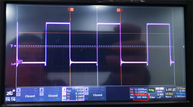
When MOS is not soldered, the gate waveform of (Q5, Q6) is normal, as shown in the following figure:
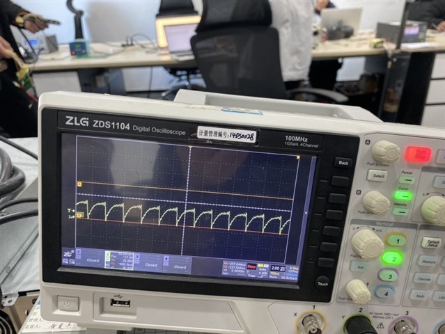
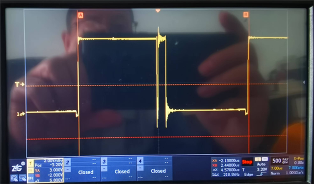
After welding Q5 (single MOS), the waveform distortion is severe, as shown in the following figure
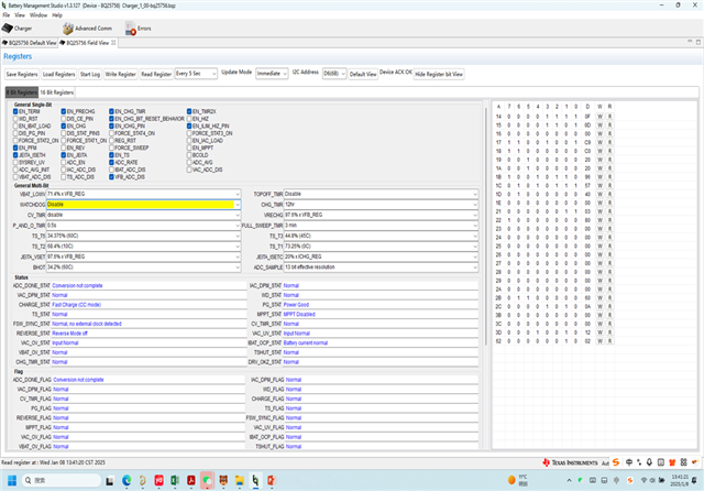
Through I2C and BQ studio tools, we have checked the chip's working status and found that it is normal. Please help us investigate the issue as soon as possible.
Additionally, could you please help us evaluate a few issues
Q1. What is the maximum distance that BQ25756's driver can support? (Distance between IC and MOSFET)
Q2. Does the BQ25756 chip solution not support double-sided PCB? Do I have to use multi-layer boards?
Q3. Is it best to use surface mount MOSFETs? Can't it be packaged with TO-220? thanks.
Hello Liu,
Q1. I would say about 3cm or 4cm.
Q2. It is possible to use a 2 layer PCB design. You would have to route most of the signals on top and have a large ground plane on the bottom. I would recommend using a 3-4 layer board just to help with heat dissipation though.
Q3. You can use either FET for the BQ25756.
I've got a few questions to help troubleshoot this:
Best Regards,
Ethan Galloway
Dear Ethan
During the debugging process of BQ25756, the upper computer monitoring showed that it entered fast charging mode, but the product did not actually enter charging state. Please refer to the attached debugging record for details. Please help to answer this ,
Condition: 1. PV external 35V/1.5A power supply.
2. The output port is connected to a 12 string battery pack, with a total voltage of 39V
3. Open the upper computer and turn off WATCHDOG
4. Enable BQ25756 and CE ports to be low. LED1/LED3 lights are on
5. The voltage of pin 24 RENG on the chip is 5V and normal
6. Chip 23 pin DRV_SUP with an additional 8.35V driving auxiliary power supply
7. Enable the upper computer monitoring to display Fast Charge (CC mode)
6. The power supply actually has no charging current (as shown in the figure below).
7. The oscilloscope detects that there is no output waveform for LODRV1/LODRV2, both of which are high
The voltage level is around 8.25V.
Please help guide why it cannot enter the charging state and how to solve it. Thank you
Condition: 1. PV external 35V/1.5A power supply.
2. The output port is connected to a 12 string battery pack, with a total voltage of 39V
3. Enable BQ25756 and CE ports to be low. LED1/LED3 lights are on
5. The voltage of pin 24 RENG on the chip is 5V and normal
6. The chip's 23 pin DRV_SUP with an additional 8.35V driver and auxiliary power supply is functioning properly
7. The oscilloscope monitors the LODRV1 waveform as shown in Figure 1, with a frequency of 220KHZ
8. The oscilloscope monitors the LODRV2 waveform as shown in Figure 2
Hello Liu,
Thanks for the new information.
If you are able too, can you send me the schematic of the charger to help me debug this? You can send me a friend request over E2E and then directly message the schematic to me.
Best Regards,
Ethan Galloway
Hello Liu,
Thanks for the new information. Your schematic looks good and I have a few suggestions:
Also, for your test conditions, I'm having trouble reading the differences between the tests. Can you highlight the test differences?
Best Regards,
Ethan Galloway