LM5143A-Q1: Current Imbalance Observed in LM5143A-Q1 4-Phase Synchronous Buck

Part Number: LM5143A-Q1

Tool/software:

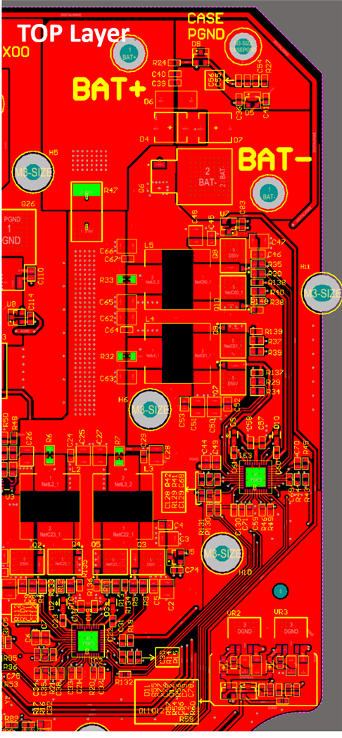
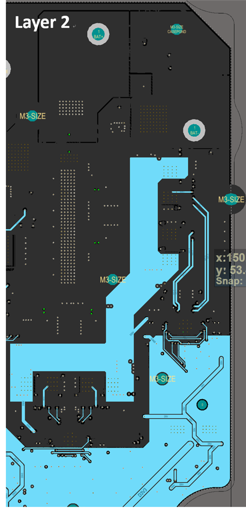
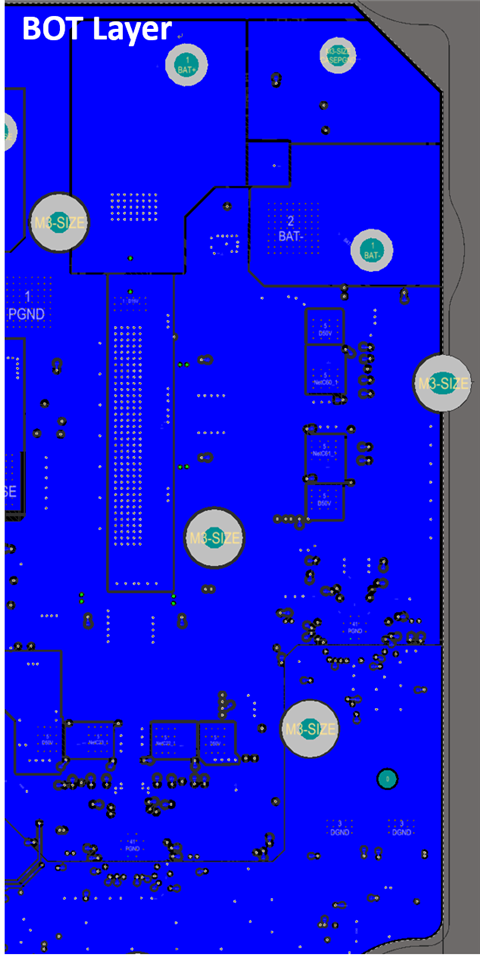
Using the 4-phase synchronous buck configuration,

Please find the schematic and quickstart design below.

7127.BUCK CONVERTER.pdf

LM5143A-Q1 Quickstart Design.pdf

we observed the following:

In DEM mode with Vin = 50 V, Vout = 15 V, and output current of 10 A, we observed that most of the current flows through Phase 2, resulting in its temperature being about 20 °C higher than the other phases. Meanwhile, the temperatures of Phases 3 and 4 are lower, indicating that the current distribution is not balanced.

Could you please advise how to improve the design so that the current is evenly shared across the four phases?


Best regards,

YUMING

  • Hello Yuming

    Could you please share your PCB layout file for review? As per my understanding schematic design is same as we discussed over  (+) LM5143A-Q1: Technical Questions Regarding LM5143A-Q1 2-Phase / 4-Phase Synchronous Buck Operation - Power management forum - Power management - TI E2E support forums

    Thank you 

    Regards

    Onkar Bhakare

  • Hi Onkar:

    Thank you for your reply. We believe we have identified the root cause of the issue. It appears that the inductor used in Phase 2 is slightly different from the others. When we swap the Phase 2 inductor with one from another phase, the MOSFETs in the swapped phase show higher temperatures. This indicates that inductor variation is likely contributing to the current imbalance among the phases.

    We would also like to share part of our PCB layout for your review. The design is based on a 4-layer PCB, with all components placed on the TOP layer. The 50 V input (Vin) is routed on Layer 2. For thermal management, the PCB is mounted to an aluminum enclosure with thermal paste to aid heat dissipation.

    During testing at an ambient temperature of 24 °C and Vin = 50 V, the maximum load current we can achieve is 48 A. At this operating point, the MOSFET case temperature reaches approximately 135 °C.

    Could you please advise on what modifications or improvements—such as PCB layout optimization, thermal management enhancements, or MOSFET selection—would be necessary to achieve 70 A load current at Vin = 50 V?

    Thank you 

    Regards

    YUMING


  • Hello Yuming

    After inserting FET parameter in the QuickStart estimated efficiency looks quite poor.

    here are some suggestions on optimization

    1. Reduce Rg to 1 Ohm or lower
    2. Bottom FET with lower Rds on could be chosen or two FETs can be connected in parallel
    3. Switching frequency can be reduced, however output filter and compensation will need modification accordingly  

    Thank you

    Regards

    Onkar Bhakare

  • Hi Onkar:

    We are currently using the ISC0805NLS MOSFETs, and the calculated efficiency is shown in the figure below. At present, the gate resistors for the high-side MOSFETs have been adjusted to 3.65 Ω and 0 Ω, while for the low-side MOSFETs, both gate resistors have been set to 0 Ω.

    Our design target is to achieve 15 V / 70 A output with Vin = 50 V. However, in our current testing at ambient 24 °C, we can only reach a maximum of 48 A load, at which point the MOSFET case temperature rises to about 135 °C.

    We would like to ask for your support in reviewing our PCB layout. Could you please advise if there are any areas where the layout should be improved to help optimize thermal performance and enable us to reach the 70 A load target?

    Regards

    YUMING

  • Hello Yuming,

    To improve heat dissipation, I recommend increasing the area of the VIN power plane on Layer 2. Additionally, consider increasing the PCB layer count to six layers and using a copper thickness of 2 oz. What is the current thickness of copper in your PCB?

    High efficiency is critical for achieving for managing better thermals. With an efficiency of 91%, approximately 100W of power will be dissipated into the PCB, which is substantial for a four-layer board. Even a small improvement in efficiency can significantly reduce thermal stress – for example, a 2% increase would reduce losses by 20W (0.02*15*70 = 20W).

    Thank you

    Regards

    Onkar Bhakare

  • Hi Onkar:

    Thank you for your suggestions. We will discuss them internally. You may close this topic for now. Thanks.

    Best regards,

    YUMING

  • Thanks Yuming

    Regards

    Onkar Bhakare