This thread has been locked.

If you have a related question, please click the "Ask a related question" button in the top right corner. The newly created question will be automatically linked to this question.

tps5420

Other Parts Discussed in Thread: TPS5420, SWITCHERPRO

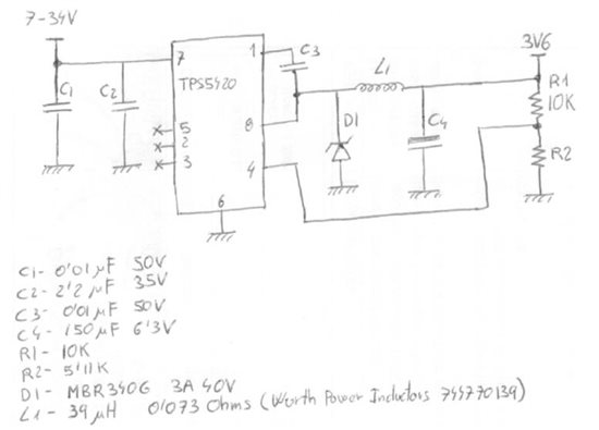
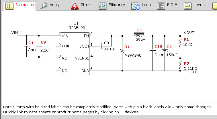
Hello, I am using TPS5420 to convert 12VDC at 3.6VDC 2A. With them food a GSM modem (Sierra Wireless Q26RD). I connected the circuit suggested by the simulator SitcherPro. I wired the circuit to test it manually. The output voltage is correct (3.58V). The problem is that after a few seconds to start the modem the voltage collapses. It seems like he could not provide strong enough. Modem consumption than 2A. It is not the appropriate component for any reason?

thank you very much

  • Hi Sergio,

    Could you clarify that the load current can be more or less than 2A (The device is capable of handling peak currents of 3A)? Can you attach the schematic that SwitcherPro came up with? When the output voltage starts to collapse it usually means that the part is going into current limiting. Could you monitor the output current to see the threshold where the voltage starts to collapse? Could you also monitor the output voltage with a O-Scope? How are you controlling the enable pin?

    My initial thoughts are; that it going into current limiting or the input power supply it reaching its set current limit. Also if you start the up the device with a load current close to its limit it will not start up and will be current limiting.

    I look foward to hearing back from you.

    Thanks and Best Regards,

    Jacob Ontiveros

  • 1258.Circuito.pdf

    Hi Jacob, Thank you very much for your quick response. I have simplified the load. connecting a resistor of 2.2 Ohm the output voltage is down also. I am attaching the schematic and the components used. The enable pin is in the air. It seems the problem is simpler. I suppose a mistake in the selection of components, but I do not see what could be the error. Where you think might be the problem? Thank you,

  • Hi Sergio,

    The calculated LC looks okay, and should give a cutoff frequency around 14kHz, which is in the stable region for the TPS5420 (3kHz-30kHz). The other thing that might be be an issue is the max ESR for the ouput cap. Did you use the one that SwitcherPro suggested? Are you using an EVM or is this on your custom board? How are you powering the supply to the device? Could you try another supply if possible?

    Thanks,

    Jacob

  • Hi Jacob, I'm traveling until Friday. I'll check the ESR of the output capacitor. The circuit is wired by hand with fine wire (handmade) and not very well. (this may affect the current limit?) suplies powering the power supply with a laboratory 5A 12VDC. On Friday I'll try to connect to a 12V 7.2 Ah battery. thank you very much

  • Hi Jacob, The circuit is working properly. I rewiring the circuit being more careful with the cables. The problem has been fixed. I will also buy another capacitor because that job is not adequate. Thank you very much for everything. a greeting

  • Hi Sergio,

    Excellent!! Glad to hear that it is working now. Check the ESR of the output cap, it will affect your loop response, and may lower your phase margin. As always, we are here to help :)

    -Jacob