This thread has been locked.

If you have a related question, please click the "Ask a related question" button in the top right corner. The newly created question will be automatically linked to this question.

UCC2802 - Current Sensing Problems?

Other Parts Discussed in Thread: UCC2802, UCC2804

I am working with the UCC2802 Current Mode PWM controllers. I currently have a buck converter design that is based on a previous design that was supplied to me. It is designed to operate at a switching frequency of 11kHz and step 300VDC down to 12.5VDC. I have very good output voltage regulation when the output does not go above a 2.5A load or 30W. The problem is that the converter is designed to have a maximum output of 10A or 125W.

While the converter is operating normally it has a nice 11kHz PWM gate drive. As the load is increases the switching frequency transitions to about half of what it should be and the output voltage begins to drop. What other reason would there be for the controller not to be running at my fixed switching frequency, is it a current limit problem? There also appears to be a problem with the controller when it needs to go above a 50% duty cycle.

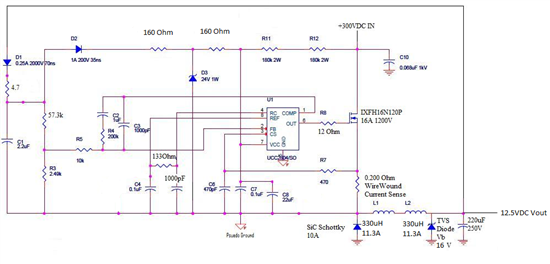
A schematic of a 48V version of the converter that uses a UCC2804 is attached6648.48V Supply Rev3 Schematic.pdf. This is the design I am working off of. I have made neccissary changes for operating within my parameters except for the current sense and comp sections of the circuit. An explanation of why the converters do not run at their set 11kHz frequencies and an explanation of the current sense and over current thresholds section of the datasheet would be very helpful.

  • Paul,

    Redraw the schematic with the values including inductances and capacitances that you are using and the voltages that you are using. Include the current rating of the inductors.

  • Here is the updated schematic the way it is working now. It does regulate the output voltage well from an input voltage of 300VDC up the max that I can currently supply of 620VDC and will need to be tested up to a DC input of 900V. However as mentioned before it does not operate at a fixed frequency and cannot supply the necessary current. The current limit of my input supply is set sufficiently high and can easily supply 1500Watts at 300V input.

  • Paul,

    This does not correspond to what you were asking about.

    Please provide teh schematic that corresponds to these requirements:

    I am working with the UCC2802 Current Mode PWM controllers. I currently have a buck converter design that is based on a previous design that was supplied to me. It is designed to operate at a switching frequency of 11kHz and step 300VDC down to 12.5VDC. I have very good output voltage regulation when the output does not go above a 2.5A load or 30W. The problem is that the converter is designed to have a maximum output of 10A or 125W.


  • Sorry for the confusion. I am working on a 12V version and a 150V version. The 150V version shown in the previous schematic exhibits the same unstable switching frequency and never runs above 5.6kHz even though it regulates the output voltage well from 300V input up to 620V input as long as the load curent is not much more than 0.75A.

    The schematic below is for the 12V version.


  • Paul,

    The first thing to do is get rid of the 0.2 ohm wire wound current sense resistor. It will have a high imductance. Use a ceramic low ESL resistor. 

    Second thing  Read the pin discriptions on page 5 of the spec with respect to the RC pins!!!.

    Make the necessary corrections and retry.

    John

  • I have been over the datasheet pin descriptions thoroughly before posting and have already previously verified my frequency calculations and timing RC on the boards. The timing resistor text in the schematic for R6 is a typo and is 133k Ohm resistor and not 133 Ohm. I am also aware that a wire-wound resistor should not be used for current sensing. The 0.200 Ohm 1% resistors I am using are designed specifically for current sensing and are non-inductive.

  • Paul,

    A quick analysis of your circuit shows that at 30 watts out with absolutely clean waveforms you will be getting 0.645 volts on the CS pin. If you were to succeed in getting your 125 watts out, the CS pin would be seeing a peak of 2.165 volts.

    Obviously with a 0.9 to 1.1 volt limit on the Cs pin you are going to somewhere in here start missing cycles as the converter goes into peak by peak current limit. I would expect that you are having issues with the current sensing. Start by putting a second 470 (or less) resistor across C6 and see how that improves performance.

    Even though this is current mode control the L/C resonance of the output capacitor and the inductor is around 2 kHz which is near the roll off of the feedback loop. You might want to look at that.

  • Could you please explain how you derived the CS voltages above in your previous post. All of my attempts to calculate it have not worked. I understand placing a second resistor across C6 would create a voltage divider but shouldn't only R7 need to be sized because of the 200nA biasing current? I am only an undergrad researcher so if you could also give me a quick explanation of how the Comp and FB specifically the Gain noted in the datasheet that would be very helpful Thank you.

  • Paul,

    Assume the current through the inductor is constant (the inductor current in this case is continuous) except for the ripple and equal to the load. calculate the ripple current and add half to the effective load current. That times the sense resistor is the current sense voltage. 

    The current gain in the data sheet is the ratio of resistors from COMP to the PWM comparator.

    Read the attached


    sem 300 compensation.zip