This thread has been locked.

If you have a related question, please click the "Ask a related question" button in the top right corner. The newly created question will be automatically linked to this question.

TPS61025 - Series resistor to add ESR?

Other Parts Discussed in Thread: TPS61025, TPS61220, TPS61070

I am using a TPS61025 for power management on a board that is draws a max of 20mA, and usually draws an average of 150µA.

The capacitor I am using on the output has an ESR of about 5E-3 at 600kHz.

Reading through the datasheet, I see that the chip "prefers" an ESR of > 30mOhm for stability.

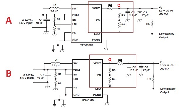
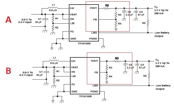
I have a layout with a zero Ohm resistor leading right out of the output of the TPS61025, before the capacitor.

I have three questions:

- My prototype works now. Should I bother at all adding extra resistance to compensate for the lack of ESR?

- Would it work to put a series resistor in the position that is now 0 Ohm, or does it have to be between Vcc and the output capacitor? I would like to try to avoid a new layout.

- Would a resistor of 0.2 Ohm be too much? I investigated, and resistors of lower value were ten times as expensive, and I would like to keep costs down, if it does not affect performance.

Thanks for the help!

  • Please read the ground rules post at the top of this forum for tips on titling your posts.  I have re-titled yours appropriately.

    Why do you use this huge IC for a 20 mA power supply?  The TPS61070 or TPS61220 would be far better choices, being lower current devices.

    But yes, ESR in the output cap is required for stability of the TPS61025.  This is why we use a tantalum output cap for it.

  • Just curious...
    The datasheet of TPS61025 says:
     
    The device is not designed to operate with ceramic capacitors only, unless a discrete resistor is added in series
    with them to replicate the required ESR. Large amounts of low ESR capacitance on the output causes instability.
     
    If the feedback resistor R3 in the schematic below is connected as in converter B, can you consider the "zero Ohm resistor" R0 as a replacement of the required ESR? Or will it be still instable? Of course the voltage on point Q is than regulated and not the voltage on the output capacitor...
     
  • Regarding the zero Ohm resistor: it is defenitely not exactly zero Ohm. All resistors have tolerance and also the tracks and soldering will give some milliOhm.

    Maybe that's why the converter still works?

  • R0 would produce the required ESR but adds the additional issue of more impedance between the output caps and the internal switches.  This will cause more stress across them from the switching action.  i.e. the loop from the output cap through both switches and back to ground is the critical loop for a boost converter that should have the least impedance.

    Your circuit probably is working because you are in power save mode.  Stability is better in power save mode.

    I recommend using a different IC for your low current power supply.