This thread has been locked.

If you have a related question, please click the "Ask a related question" button in the top right corner. The newly created question will be automatically linked to this question.

BQ24031

Other Parts Discussed in Thread: BQ24031, BQ24071, BQ24079, BQ24030

Hello,

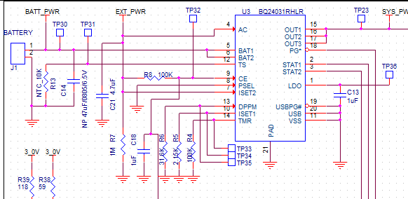
We designed in the BQ24071, but now have realized we need the charge voltage to be at 4.1V instead of 4.2V.  The closest thing I could find to a drop in replacement is the BQ24031, which may work depending on how AC mode works.

The device has 2 power inputs, but I would only use 1. The power inputs found on the BQ24071 correspond to the AC inputs on the 24031.  So if the AC input on the BQ24031 can be made to act like the power input on the BQ24071, it would drop in (USB and USB PG would be grounded in my case).

So, one thing I need clarification on is if when the BQ24031 is powered up from AC input, does the device follow USB boot up mode and limit the current to 100mA for a short period as the USB boot up feature describes?  Table 1 of the BQ24031 datasheet shows the USB bootup feature is enabled for AC mode with PSEL low, but the datasheet does not specifically mention if current is briefly limited to 100mA in AC mode.

Thank you,

Jamaal

  • Was bq24079 not a good fit?

    If you are grounding USB, PSEL need to be high.

  • Hi Jeff,

    The BQ24079 may work, but it is not pin for pin.  I need to verify how I configure the BQ24031 to replace the BQ24071. Should just be related to the AC/USB pins inputs. Otherwise things look very same/similar except for the 4.1V float.

    Thanks

  • I do not have a bq24031 EVM in house to confirm the USB boot up.  But, per note 12 on page 6:

    With the PSEL= low, the bqTINY III-series defaults to USB charging. If USB input is ≤ VBAT, then the bqTINY III-series charges from the AC input at the USB charge rate. In this configuration, the specification is 400 mA (min) and 500 mA (max). 

    Is 500mA the max you want to charge from AC input?

  • Hi Jeff,

    Yes.  I want the 500mA max.  However, is there a typo in that note.  It doesn't reference the BQ24031:  “ USB input current range, (USB) bq24030/32A/35/38(12)”.

    The big question is if I will see the 100mA boot up limit throught the AC input (I hope we do).

    Recall, I have a design where I use the BQ24071 and want to know if I can just install the BQ24031, noting that the USB and USBPG will be grounded, and the charger will act the same.

    Thanks

  • I am in the process of locating a bq24031 EVM so that I can confirm operation.

  • With PSEL=low and power applied to AC, the input current is limited to 100mA for the first 150ms.

  • Thanks Jeff!

    That is great news.  From a HW perspective, I want to verify that I should be able to replace the BQ24071 with the BQ24031.  I believe it will work, but I wanted to check with TI first.

    Thanks again

  • Hi Jeff,

    We have replaced the BQ24071 with the BQ24031, and we are seeing one discrepancy we can't account for.  The charge termination current should be in the range of 13mA to 35mA.  The termination calculation is identical between the two parts, but with the '71, the charge current trips at 16mA, but the '31 trips at 5mA, which is out of spec. 

    We could change the Rset resistor potentially, but would rather not, and we'd like to understand this difference if possible.

    Thanks

  • bq24071 and bq24031 are essentially the same IC, with the 71 having one output disabled.  Their specs are slightly different but in both the KSET value widens for low values of IOBAT.  So, once you include the variations of KSET, VTERM and RSET, are you still out of spec?

  • Yes,

    We had a working design with the '71, and then dropped in the '31 (we only use the USB input).  With the same components, Rset of 2.15k, we see different results, with the '31 being out of spec.

  • Was the MODE=PSEL pin high with the 71?  If so, your V(TERM) voltage would have been 250mV typical with the 71.  Now, with PSEL low on the 31, you are now using the V(TAPERUSB) spec (which should actually say V(TERMUSB)) which is 100mV typical.

  • Hi Jeff,

    We figured out that issue.  It turned out our wall supply was not working properly.  We replaced it, and got passed that problem.  However, we have a couple other questions.

    From the '31 datasheet, ITERM range is 10-150mA, and IPRECHARGE range is 10-150mA.  Are these typical values, or max values (Including tolerances in the calculations). The reason we ask is that we are considering 820 ohms for 200mA (MAX) on IPRECHARGE (typ ~140mA). Is this ok?

    Also, with the BQ24031, we are seeing some unexpected "charger not charging" states from the STAT1 and STAT2 pins.  They appear randomly during long charge tests. Our charge timer is set at 100k (~10 hours), and out VTS went as low as 600mV.  So, I don't think this is from charge timer or thermistor. The "charger not charging" states occurred at ~40 minutes for one test, and 3 hours for the other.  While I need to see if we are still having some wall adapter problems, is there any way this could be induced by grounding USB and USBPG?  I want to verify that I can ground those inputs to drop in for a BQ24071 replacement.

    Thanks!

  • Regarding the current range, the values in the datasheet are min and max over temp that TI warranties (i.e., that we have tested).  The accuracy will be less outside of that range.

    Regarding the random STATx pins, I am not aware of an issue like this but will investigate further.

  • Hi Jeff,

    Another question...if I set my charge termination to 74.5mA with a 604 ohm resistor, which causes precharge to be 186mA, what will happen to the precharge current since it is above the indicated range?

    Thanks

  • Those ranges are what we test in production.  In general, the IC will operate slightly outside of those ranges without issue, except for slightly worse accuracy.

  • Hi Jeff,

    We are testing the BQ24031 in this setup, and have found a strange issue.  If the battery voltage is above 3V, and we start charging, the part works as expected.  However, if we start charging below 3V, when it transitions from below 3V to above, the charger doesn't limit ICHARGE to 500mA. 

    Is this expected?

    Just as a reminder, we have ISET 2 tied to VBUS, ISET 1 to 802 ohms, VUSB grounded, and 5V on AC,

    Thanks

  • Hi Jamaal,

    Is your VBUS refer to the AC input? When you mean VUSB grounded, do you mean you connect VUSB to the ground? Please let me know so I can verify on our bench. Thank you.

    Regards,

    Jing

  • Thanks Jing,

    Correct, we have Vusb tied to ground.  The idea is to have a 4.1V version of the TPS24071.

    Jamaal

  • Jamaal,

    I have tested with our EVM. I used a 825 ohm resister (closest I can find in our lab) for ISET1. Other test conditions are the same as you mentioned above. In addition, the PSEL pin are pulled low so it is in USB mode. When the battery voltage is less than 3V, it is in the pre-charge state. Therefore, the charege current is approximately to be 120 mA. Once the vltage increase to 3V and above, the charging stage goes to fast charge and the charging current is 500 mA with the test conditions. I have verified on the bench and did not see the problem you descibed. Please let me know if you have other questions. Thanks.

    Regards,

    Jing

  • Thanks Jing,

    We are seeing very similar results, expect during fast charge, the current jumps to 800mA.

    Here's the implementation of it, except R5 would be 820 ohms. EXT PWR is directly connected to USB voltage. STATs, CE, and PG go to micro inputs.

    On the EVM, similar setup, this issue doesn't occur. I have my setup supplying a battery simulator which corresponds to a resistor, diode and external power supply. The diode is connected from the PS to the resistor and the battery inputs across the resistor. Its not the simulator, as the eval board doesn't do behave the same.

     Here's what's happening:

    1) I have USB on the AC input, as this is a drop in replacement for the BQ24071 and the pins work out that way.

    2) I am trying to set a termination current of ~50mA, which results in a fast charge in AC mode of 1.2A. I have PSEL grounded, which should limit the input current to 500mA, and charge current should be less due  to system load ~100mA. I believe I shouldn't see anything above 500mA input c urrent

    3) This works fine if I start charge while the simulator is above 3V precharge/fast charge transition.  I charge is <500 mA as expected.

    4) If I first start in precharge, precharge current is 132mA as expected, but as I transition to fast  charge, charge current jumps to 800mA or so and is not limited to 500mA

    5) Not sure what else fixes the part in USB current  limiting mode, PSEL is grounded on my PCB.

    Thanks for your help

  • Hi Jamaal,

    When you calculate the resistor value for ISET1 using I(TERM) = (V_TERM *K_SET) / R_SET, what is the value you used for V_TERM. There are two different V_TERM, V_TERM(AC) and V_TERM(USB). Since you connect USB voltage to the AC input of the IC, V_TERM(AC), which is 25 Mv, should be applied to the equation. Then the ISET1 resistor should be 2.125 kohm.

    Also, according to table one in the datasheet, When AC input is present and USB input is absent, PSEL is high, then maximum charging rate will be set by ISET1. Therefore, if you set PSEL hight, and change the ISET1 resister to 2.125 kohm, the charge current should be 500 mA and the pre-charge current should be around  50 mA as well.

    Please let me know if this helps.

    Regards,

    Jing