This thread has been locked.

If you have a related question, please click the "Ask a related question" button in the top right corner. The newly created question will be automatically linked to this question.

TPS70933 enable

Other Parts Discussed in Thread: TPS54040

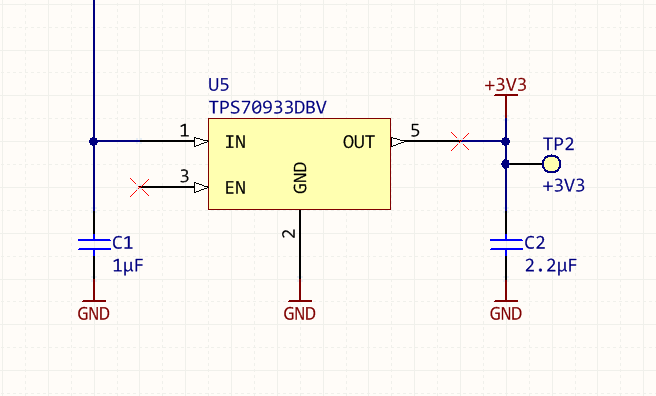
I have a number of boards using the TPS70933 LDO.  As per the data sheet I have left the ENABLE pin floating (internal pull-up only) with an input voltage of 8V but in all cases the output from the regulator is around 0.7V unless I manually pull up the ENABLE pin externally.  When measured the voltage on the ENABLE pin is around 0.4 - 0.5V which does seem to be well under the 0.9V enable pin high value.

Is there some other minimum operating voltage before the enable pin pull-up starts to behave as specified or will I need to add an external drive to this signal?

  • Hi Timothy,

    You are correct that there is an internal pull-up on the EN pin.  The device should enable if you float the EN pin.  We use this feature on the TPS70933EVM.  When you measured the voltage on the enable pin, did you use a high impedance prove?

    Very Respectfully,

    Ryan

  • When measuring this value I just used a Fluke multimeter which is specified have an input impedance of around 10M.

    On all of my boards (one more or less constant desgin but spread over five different boards) I have the TPS70933DBV with pin1 connected to the input voltage (8V in this case) with 1uF input capacitance, pin is GND, pin 3 (EN) is floating, 4 is not connected and 5 drives the external circuitry with a 2.2uF capacitor located quite close to the output pin.   The 8V is generated off board by a TPS54040 switcher.

    At present no board has started up without me connecting the enable pin to some voltage > 0.9V (usually using a simple divider to the input power supply). 

    Below is the relevant schematic and PCB layout for this part.

    Any suggestions?

    Tim

  • Hi Tim,

    10M impedance is still low enough to pull down the voltage, likely the actual voltage on the enable pin is a bit higher.  This of course does not yet explain the behavior.

    We know the enable circuitry is not damaged, otherwise you should not be able to enable the device using an external voltage source either.  Your layout looks fine and should not be causing any issues.  I benched one of our EVMs with your input conditions and it enabled via the internal pull-up.  

    Would it be possible to send me a board to bench?  

    Very Respectfully,

    Ryan

  • Hi Ryan,

    I have also used TPS70933DBV on several designs with a floating enable line. Some of these designs are in production. I have just received pre-production samples of another design which has been fine all thorough the prototyping stage but now there is no 3V3 output from the TPS70933DBV on the pre-production samples. I have replaced the TPS70933DBV with some older stock I have and they work fine. Also if I connect 5V to the enable line of one of the pre-production boards the 3V3 rail appears.

    The input voltage is 24VDC.

    Was there any resolution to this issue that you can share?
  • Lee,

    The issue I found seemed to be due to what could best be described as grey-market parts, I think.  Essentially the board loading was done overseas and parts sourcing was handled by the manufacturer.  I ended up purchasing a number of replacement TI parts (a few samples, the rest directly from Digikey) and these all works as specified.

    I did compare the parts under a microscope, both were labelled as the same part but the parts from Digikey has a much clearer silkscreen label, the parts that were supplied by the board loader had laser etched text with a much blockier font than the authentic TI parts.

    We have now stopped using that manufacturer.

    Tim

  • Hi Tim,

    Many thanks for your reply it is very useful as it confirms that your post had not uncovered an known issue with a genuine TI part.

    The PCB's I have an issue with were assembled overseas and parts sourced by the manufacturer.  It is possible that non-genuine parts have been used and we will be pursuing that line.

    Regards,

    Lee.

  • Thank you Tim and Lee for your posts. I am glad that you both were able to resolve your issues.

    A list of authorized distributors and authorized resellers can be found at the following link:

    www.ti.com/.../counterfeit_policy.html

    We also have the following e-mail: ti-counterfeit@list.ti.com

    Very Respectfully,
    Ryan
  • I am experiencing a very similar problem to the above with parts sourced from Digikey.

    Application circuit (Lets call this Prototype A) is nearly identical to what is shown above (input capacitor is 2.2uF X7R as opposed to 1uF).  Summary,

    -          Part will not produce output until some voltage is applied to enable pin (i.e. left floating, output is near zero volts).

    -          When measured, the enable pin (floating) is at or less than 0.4V (measured with Fluke multimeter).  Output is not produced either with or without multimeter connected.

    -          When enable pin is pulled to Vin, stable 3.3V is produced, however input current is between 20 to 60mA (depending on which sample I’ve measured).  Output current is < 30uA.

    -          Our application typically runs from a 9V battery, however for the above test I was running from a lab power supply in order to observe the 6.5V limit on the enable pin (tests were done at 6V).

    When I pulled parts from a previous prototype (Lets call this Prototype B - parts purchased much earlier in the year) and put these on Prototype A boards, the parts appears to be working as described in your datasheet. 

    I have at least 8 prototypes (Prototype A) experiencing this behaviour.  Although I will admit some of these were run at 9V, and not the 6V as described above.  But I have swapped the regulator on two cards several times from parts directly from a bag from Digikey (purchased Oct 19, 2015, Part number TPS70933DBVR) and was sure that we observed the 6.5V limit on the enable pin.  Also, when Prototype A parts are put on Prototype B boards, they don’t produce power unless the enable pin is pulled up (I haven’t made further measurement for this setup).

    From the above tests, I can only conclude that the parts from Digikey are bad.  Part markings from both the Prototype A boards and Prototype B boards are “SDG”.  The only difference between the parts that I can tell is the placement of the horizontal lines on the parts.

    My question is then, is there a legitimate batch issue with these parts?  Or is my conclusion incorrect? How do I tell if they are TI parts or not?

    Attached images:

    -          With “G” underlined – Prototype A (questionable parts).

    -          With “D” underlined – Prototype B (working parts).

  • Hi Timothy,

    Sorry about the delay. From your description of Prototype A, the supply current is higher than expected which implies that there is a leakage path on the Prototype A devices. The internal pullup on enable is fairly weak and could be defeated with an unintentional leakage path. Thank you for providing the images of your boards. It appears that your Prototype A boards have excess flux that could be the cause of the leakage path. I do not see the flux on your Prototype B image that you say is working fine. If the flux is removed, do the Prototype A boards work?

    Very Respectfully,
    Ryan
  • Hello,

    Prototype A cards had excessive current drain when they arrived right from the board shop.  Remember also that we saw this repeatedly on several cards.  So I don’t believe contamination to be the cause of excessive drain (card should consume 30uA.  We were measuring approx. 40 to 50mA. 

    I believe the enable pin is a bit of a secondary problem, as when this pin is pulled to input voltage (and input voltage kept to 6V) we still see the excessive current drain.

    Remember also, that when this device is replaced with parts from Prototype B cards (should be identical parts) we have no trouble achieving our current drain targets.  We have also tried another manufacturers parts and these work fine (suggesting that this problem is truly related to the regulator and not something downstream).

    Note that the photos shown are of the sample I’ve been playing with a lot in the lab and were taken just after soldering (prior to any cleaning).  I simply wanted pictures of the package marking so I didn’t get the parts mixed up.  So yes, there is flux and debris on the card in the photo, but I assure you this is not the case when we perform our tests.


    Tim.

  • Hi Tim,

    I see that you have placed Prototype B devices on Prototype A cards and saw no issues. Have you taken Prototype A devices and placed them on Prototype B cards? If you have, did the higher current follow the device?

    Very Respectfully,
    Ryan
  • Yes,

    I can't honestly recall if we tried pulling them directly off Prototype A cards and put them on Prototype B boards.  But we definitely tried prototype B boards with parts directly from the Digikey bag (i.e. new parts).  They too had higher than normal current draw.

    Tim.

  • Hi Tim,

    As the higher current followed the device, the best option may be for some of the devices to be sent to TI so that we can further investigate. Bellow is a link to our customer return policy. There is a form that would need to be filled out and you would need to work with Digi-Key to return the devices since your purchased the devices through them. They should be able to help you with the return.

    www.ti.com/.../customer_returns.page

    Very Respectfully,
    Ryan