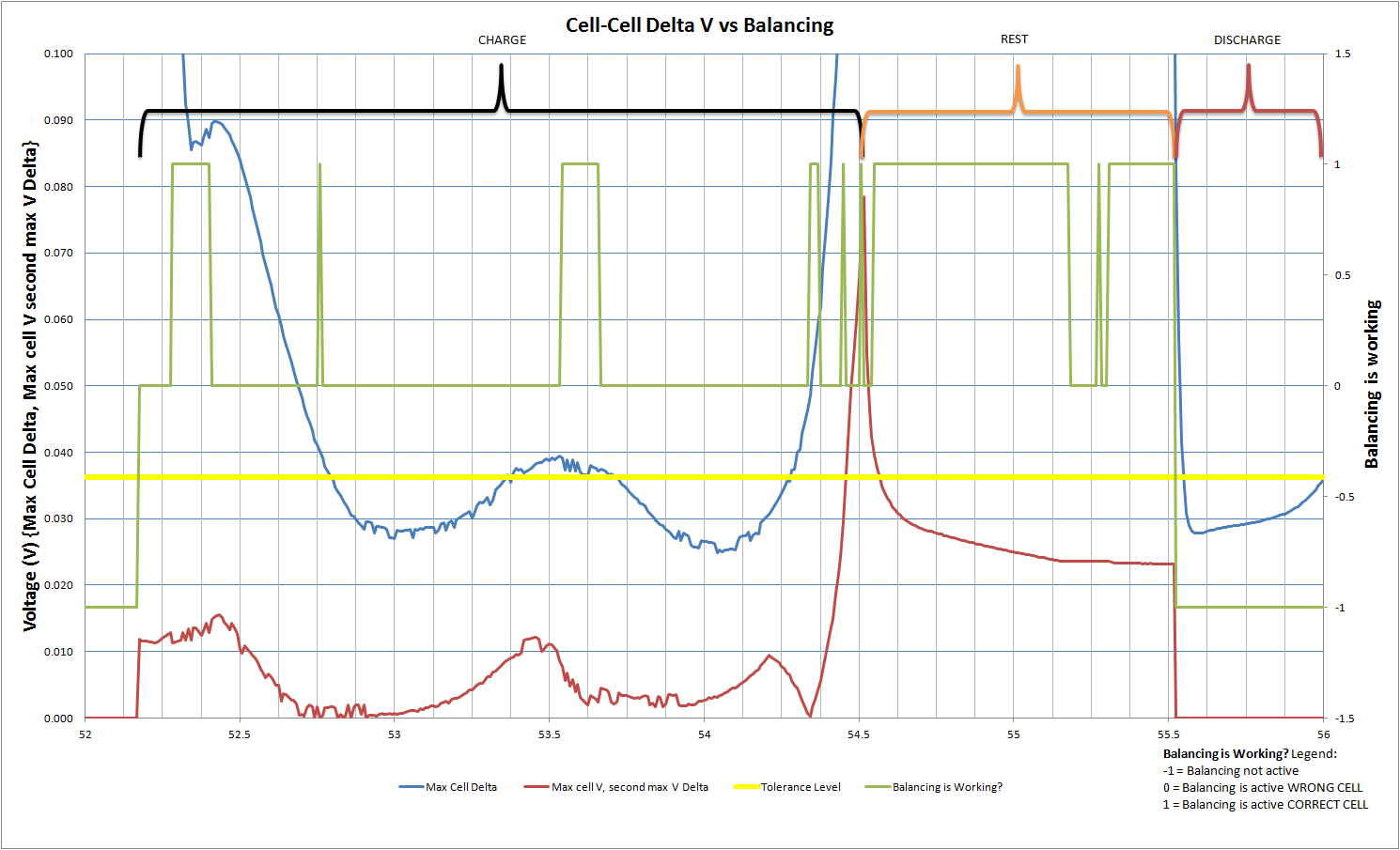
We have been doing a lot of testing on the cell balancing function of the BQ77910A. I find that during most of the charge, since we are using LiFePO4 cell the variation from the highest cell to the lowest cell is 40mV or less. The difference between the two highest cells is even less. I have included a graph below showing how the data stacks up.
I could not find a tolerance specification in the data sheet for the part. I understand the part compares all the cells and balances the highest cell, for dwell time then checks again. Could you find out if there is a tolerance? I worry we are under the tolerance and balancing is going to be spotty at best.
With all of the testing we are doing we are finding that the Balancing is activating, but not following what is specified in the data sheet. It is supposed to bleed the highest cell, sometimes it is, sometimes it jumps to a different cell. This is causing a large decrease in capacity since the balancing is bringing the pack out of balance.
Thanks,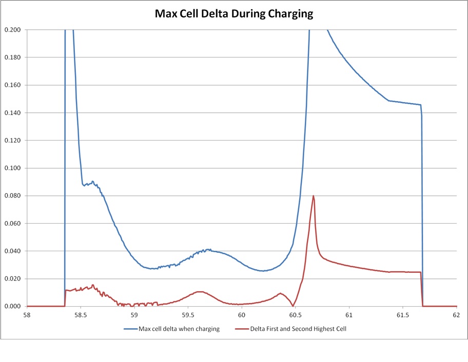
JD