This thread has been locked.

If you have a related question, please click the "Ask a related question" button in the top right corner. The newly created question will be automatically linked to this question.

TPS61163A different loads

Other Parts Discussed in Thread: TPS61163A

Hi, I have TPS61163A and I like to check with you if I'm using it correctly.

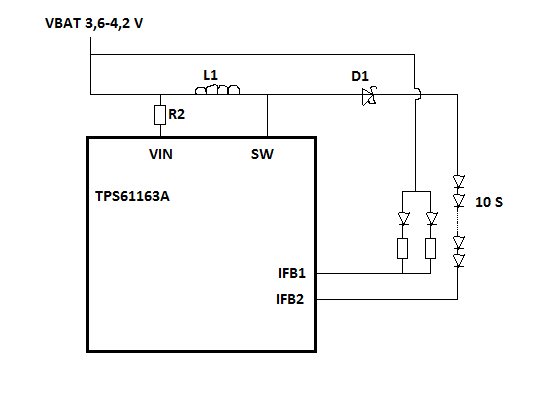
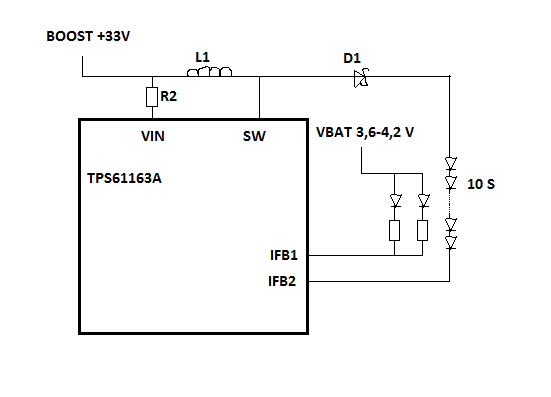
I have a boost that connects to a series of 10 backlight LEDs that I sink through IFB1.

Then I have another 2 LEDs that are parallel to each other (with 25 ohm ballast on each). I like to connect them directly to VBAT and sink them through IFB2. 

Is this setup reasonable? Should I connect VIN pin to the output of the boost for the 10 series LEDs?

[EDIT: Added image of the relevant schematics]

Best regards
Valter

  • Hello, did someone have time to look at this? Is this a reasonable way to connect TPS61163A?

  • Hello,

    I'm afraid this configuration may not work. The TPS61163A should be powered by a supply of < 6.5V. The boost circuit will boost this voltage up to VOUT=38V (at the cathode of D1) as needed. To determine the boost output voltage, the TPS61163A continiously monitors the voltage at IFB1 and IFB2 and selects the lower of the 2 as the regulation point. The feedback loop will adjust VOUT to ensure that the current sink with the lower voltage remains in regulation.

    If the settings for the 2 parallel LED configuration (connected to IFB1 on your schematic) happens to cause the voltage at IFB1 to be lower than the voltage at IFB2, the loop will try to increase VOUT to regulate IFB1 to the correct headroom. Since there is no feedback for IFB1 (VOUT is not connected) VOUT will keep increasing until it reaches OVP. To avoid this you need to ensure that IFB1 voltage will never be lower than IFB2. 

    Regards,

    Angelos Tsiros

  • Hello Angelos,

    Thanks for your reply. I realize I made a big mistake in my drawing above, the VIN is connected to the VBAT too. See correction below.

    However, I do understand the problem with the feedback loop. We will probably add some components to secure that IFB1 voltage will never be less than IFB2 voltage. Thanks.

    Best regards

    Valter