This thread has been locked.

If you have a related question, please click the "Ask a related question" button in the top right corner. The newly created question will be automatically linked to this question.

TPS62366 Oscillation when adding more Cout

Other Parts Discussed in Thread: LP8754

Dear TI

I would like to confirm an oscillation issue on web EVM of TPS62366.

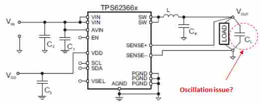
I tried to move capacitor pisition with adding line inductor.

When added Cload on EVM, output was oscillating.

Please take a look attaching file.

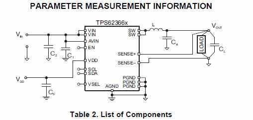
But Cload is described on datasheet page 34 OUTPUT FILTER DESIGN Figure 51.

I'd like to know how to consider Cload. And why was Cload  no good in my test on EVM?

TPS62366_oscillation_issue.pdf

Thank you and best regards

K.Narisawa  


  • It is not clear how you are connecting the SNS+/- lines. Is this done on the back of the PCB?

    Does this only occur at 5.5Vin or at lower Vins as well?

    What are you trying to measure with this test setup? There is a local load transient circuit on the EVM already. It can produce the fastest rise/fall times to best match the application.

    The wire may be forming a second stage output filter which is interacting with the main output filter and causing instability. I'm unsure why you need to add a wire in that position.
  • Hi Chris-san,

    Thank you for your kindly help always.

    SNS+/- connected on bottom EVM. Please look at attaching file.

    And this oscillation issue is not only 5.5V.Lower voltage is also same.

    Added wire is estimation for long line inductance on PCB. But actual line indactance will be lower than this test.

    How did you test on below schematic on datasheet? and how long does capacitor's location between

    C4 and CL? If you have picture on test condition, please let me know.

    TPS62366_oscillation_issue2.pdf

    I'd like to know what is wrong in my test condition?

    Thank you and best regards

    K.Narisawa


  • Thank you for these details.

    It says you test with an electronic load. Does a resistor on the output behave the same? Sometimes the electronic load induces oscillations.

    The D/S figure shows the concept for the POL regulator being some distance away from the load. This was tested on the EVM by populating C10-C12 as you have done. But the load transient circuit (the load) was used for those tests (load transient tests).
  • Hi Chris-san,

    Thank you for your kindly reply.

    I tried to test with resistor in stead of electronic load. That was same result. And lower supply voltage what was 3.6V was also same result too.

     I attached a file ,please take alook.

    Do you have any idea how should I make customer consent to no oscillation issue in TPS62366 with using EVM?

    Does any customer use in productoion?

    narisawa-k@clv.macnica.co.jp

    BTW, is LP8754 also your team? I'm asking on E2E but no response....


    Thank you and best regards

    K.Narisawa


    TPS62366_oscillation_issue3.pdf

  • I have requested an escalation of your LP8754 thread.

    Note that the EVM comes populated with capacitors in C10, C11, and C12.  I removed these and placed one of those 10uF in C7 and the other under J7 to match your latest setup.  It's not clear what your test has done with these caps--they seem present in some photos.

    I was unable to reproduce your oscillation with this test setup:

    In the photo, you can see a long white wire.  This is the inductance I added.  The load is a decade box connected with the red wire across the through hole resistor on the output.

    I measured the output voltage at J7.  Where do you measure it?

    You might try a twisted pair set of wires for the sense connections.

    As well, I found the stability/ripple easier to evaluate in forced PWM mode.  I see almost 0 ripple at J7.

  • Hi Chris-san,

    Thank you for your support.

    I'll try to do that on next Monday. I'd like to ask you one question. Do you add load capacitor (Cload) in photo?

    I know no oscillation issue without load capacitor.

    I guess Cload affect oscillation issue when sns +/-  are connected to happen delay for feedback loop.

    How about is your opinion?

    I'd like to check TPS62366 on system level when other IC( with the input capacitor ) is connencted whether it have oscillation issue or not.  


    Thank you and best regards

    K.Narisawa

  • Yes, I installed a 10uF cap behind J7. I should have installed it across the SNS leads on that leaded resistor. I'll check this next week.
  • Hi Chris-san,

    Thank you so much for quick response and kindly reply.

    Oh.. it's good news.

    I'll check it with twist pair wire on next week. 

    This great your support is my strong item to get socket and make a good relation with customer.

    Thank you and best regards

    K.Narisawa


  • Hi Chris-san,

    Thank you for your support always.

    I checked with your connection in your photo, and result was no oscillation issue.

    But it was different schematic between yours and mine.

    I attached test schematic and please take a look.

    And also checked PWM with 1A from electrical load.

     TPS62366_Test_Result.pdf

      Could you please check it on your side?

    Or can you check it on simulation too?

    Thank you and best regards

    K.Narisawa 

  • Yes, the added cap at the output after the inductance is forming a second stage filter. This is causing the oscillation. With my longer white wire I used to add inductance, I see a larger oscillation. Here is a paper on second stage filters, by a well known author: www.switchingpowermagazine.com/.../1%20Second%20Stage%20Filter%20Design.pdf

    You can compute the estimated inductance from your wire and compare it to the estimated inductance from a PCB trace. I think that it is possible that your wire gives much higher than any PCB would ever see. I have not heard reports of this behavior before.

    As a quick test, adding a 100uF ceramic at the IC output greatly reduced the oscillation magnitude and made it more stable in general. This agrees with the theory. The 100uF cap reduces the loop bandwidth.
  • Hi Chris-san

    Thank you so much.

    I understood.

    First , I will read a paper well and then if I have more question,

    Please help me again.

    Thank you and best regards

    K.Narisawa