This thread has been locked.

If you have a related question, please click the "Ask a related question" button in the top right corner. The newly created question will be automatically linked to this question.

TPS62736EVM-205 User adjustable output voltage via resistors

Other Parts Discussed in Thread: TPS62736EVM-205, TPS62736

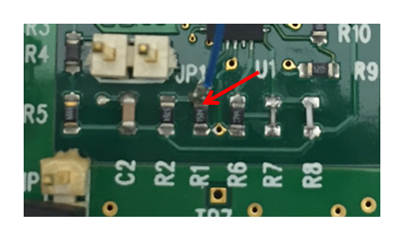
I just received a TPS62736EVM-205 from TI with the REV B PCB Layout.  One of the listed features (www.ti.com/.../tps62736evm-205 Documents) is that it has "User adjustable output voltage via resistors."  How do I access this feature?  R1, R2, and R3 are fixed on the board.  I don't see how I would have access to VRDIV, VOUT_SET, or VIN_OK_SET (Pins 7,8, or 9 on TPS62736).

  • Ajustable output means the voltage at OUT pin can be programmed by those external resistor R1, R2, and R3. You can change those three resistors to set your desired output voltage within the spec.
    For VRDIV, you can solder a piece of wire on R3 at the VRDIV side. For VOUT_SET, you can solder a piece of wire on the other side of R3. For VIN_OK_SET, you can solder a wire on R2. Please refer to schematic in the User's Manual page 3.
  • I'm familiar with the schematic in the User's Manual page 3 (Figure 1). However, on TPS62736EVM-205 R1, R2, and R3 are not external. They are already soldered via surface mount onto the evaluation board. There is no place on the board to solder a wire is there? How would I do that? It does not seem to me that the board is designed to do that.
  • you can solder the wire on the resistor pad as far as it makes contact. For example, like the blue wire in the figure below.

  • Thank you. I need to remove the resistors correct?

    Just FYI, the whole reason I bought an evaluation board is so I didn't need to solder this circuit. Describing the evaluation board as having a "User adjustable output voltage via resistors" as a feature (www.ti.com/.../tps62736evm-205) seems a bit misleading when it means I need to disassemble the board and rebuild it. I was expecting there would be headers for R1, R2, and R3, just like there are for IN, IN-SENSE, OUT, OUT-SENSE, GND, VIN_OK. and jumpers to engage the fixed resistors. Otherwise "user adjustable" doesn't really seems like it should be included in he description of this part.
  • You do not need to remove the resistor. As shown in the picturen you can just solder it on the resistor.

    As I mentioned before, for almost all of our converters, if you can refer to the datasheet,  the word "adjustable" means you can externally program the output voltage level by resistors. The output regulation is not internally fixed. Thank you for your feedback, and we will continue to improve the user experients of the EVMs.

  • "You do not need to remove the resistor. As shown in the picturen you can just solder it on the resistor."

    Sorry, I am a little confused by this comment.  Could you please explain how the circuit would work with external resistors if I didn't remove the fixed resistors?  As shown in the figure you have referred to R1, R2, and R3 are fixed into the circuit of the evaluation board.  The out put can be adjusted by choice of R1, R2, and R3 by the following equations:  VOUT = VBIAS((R1+R2+R2)/(R1+R2)) and Vin_OK=VBIAS((R1+R2+R3)/R1) and R1+R2+R2  ~=13MOhms.  If I did not remove R1, R2, and R3 they would still be part of the circuit.  I understand how to correctly change the output by replacing R1, R2, and R3 with the the correct resistors to achieve the desired output, but I am not sure how to easily achieve the correct output by leaving those resistors as part of the circuit and then adding more external resistors.  

    Thank you for taking my feedback.  To further clarify, I guess I just don't think the word "adjustable"  seems appropriate when soldering is involved for that adjustment especially if parts need to be removed and replacement.

  • Sorry for the confusion. Yes, if you would like to change the outout regulation level, you will need to change R1, R2, R3 if this is what you meant by removing the resistor.