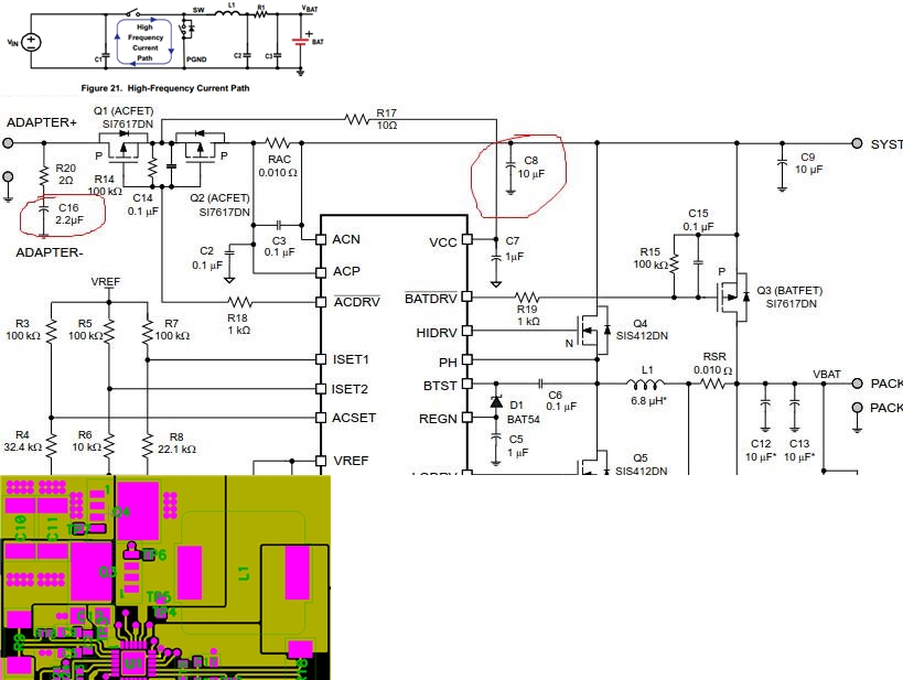
In bq24616 layout guidelines,
"Output-capacitor ground connections must be tied to the same copper that connects to the input capacitor ground before connecting to system ground."
"Route the analog ground separately from the power ground and use a single ground connection to tie the charger power ground to the charger analog ground. "
There are 1) output cap ground 2) input cap ground 3) system ground, 4) analog ground and 5) power ground total three grounds described.
Q1: The 4) analog part should refer to the buck-converter? and 4) analog ground consist of 1) input cap and 2)output cap ground
Q2: 3)system ground and 5)power ground should be synonyms?
Q3: In Gerber it is not seen how 1)input cap ground and 2)output cap ground are tied with at a single junction by start connection, and the layout guideline merely says connects together. Do they require a start/tie connection? Could it be highlighted in Gerber?
Hui


