This thread has been locked.

If you have a related question, please click the "Ask a related question" button in the top right corner. The newly created question will be automatically linked to this question.

TPS3813 floating WDI pin

Other Parts Discussed in Thread: TPS3813

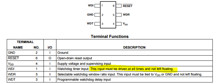
We have an application that is utilizing the TPS3813 watchdog.  We had a failure of the unit that is undergoing scrutiny trying to identify the root cause.  One of the possible failure paths is with the TPS3813.  A few lines in the TPS3813 datasheet got us questioning our design and possible cause of failure (see highlight images below).

In our circuit design, the TPS3813 WDI pin does not have an external pull-up or pull-down resistor.  The pin is connected directly to a GPIO pin.  The GPIO pin does have an internal pull-up resistor that is hardware enabled on MPU reset.  We were then questioning if the GPIO internal pull-up resistor would be active immediately on power-up or if some delay occurred before the internal pull-up became active.  To test this we wired in a voltage divider on the WDI pin consisting of 1 Megaohm legs.  The point of the voltage divider is to coerce the WDI pin into an invalid logic state so we can scope it.  The resistance of the voltage divider legs was chosen such that the GPIO pin’s internal pull-up resistor can easily overdrive them should it be active.  The test schematic is shown below.

We then scoped the VDD rail and the WDI pin on power up.  The scope traces are shown below.  The yellow trace is the VDD rail and the blue trace is the WDI pin.  The scope trace shows that the GPIO pin’s pull-up resistor does not become active until the VDD rail exceeds ~0.8 V at which point the WDI pin is pulled to VDD rail.  Below ~0.8 V the WDI pin could be potentially floating.

Here are the questions we need answers to:

(1)    What impact does a floating WDI on power-up have on the operation of the watchdog, the datasheet does not say?  Can it cause the reset pin to be asserted low even when a valid pulse train is being applied to the watchdog after power-up? 


(2)    If it can be asserted low (per question 1 above), what voltages on WDI would be needed to cause this to happen?  Is this a very repeatable event or a very rare event?  We haven’t been able to reproduce the failure so probabilities would be useful.


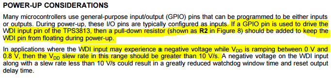
(3)    The datasheet specifies a pull-down resistor, while our circuit utilizes a pull-up resistor.  Is this a potential issue and why?


(4)    The GPIO pin’s pull-up resistor appears not to be active until VDD reaches ~0.8 V.  Is this an issue?


(5)    The datasheet also warns about negative transitions on WDI with a VDD slew rate of less than 10 V/s.  The scope plot shows that our circuit ramp rate is much higher than that.  Are there any issues here that we are missing?


Thanks


  • Hi Dan,

    The watchdog for TPS3813 is always active when /RESET is logic high. The lower boundary of the first watchdog window is disabled upon startup; however, the upper boundary remains in effect. After /RESET transitions to logic high, a valid WDI pulse must occur before the upper boundary.

    The watchdog is not able to be disabled. Some other devices can have their watchdog disabled by floating the WDI pin. The statement in the Terminal Functions table is meant to help convey that this is not the case on TPS3813.

    During startup, /RESET will be logic low until 25ms (td) after VDD crosses the threshold plus hysteresis. The pulldown resistor is used to keep WDI in a known state (compared to the GND pin of TPS3813) unless a WDI pulse is occurring. A pull-up, particularly during startup could cause WDI to remain in a middle state (not high or low) for a period of time. TPS3813 is designed for WDI to be typically low.

    The slew rate is similarly stated to keep WDI within "known" bounds and ensure that the watchdog correctly registers a pulse and outputs the correct logic level on /RESET.

    Very Respectfully,
    Ryan
  • Hi Ryan,

    Your statement "The watchdog is not able to be disabled.  Some other devices can have their watchdog disabled by floating the WDI pin.  The statement in the Terminal Functions table is meant to help convey that this is not the case on TPS3813." confuses me.  I don't see how this statement "This input must be driven at all times and not left floating." could be translated to mean that a pull-down is NOT required.  Is this an error or typo in the datasheet?

    Could you please clarify this statement: "A pull-up, particularly during startup could cause WDI to remain in a middle state (not high or low) for a period of time.  TPS3813 is designed for WDI to be typically low."  How can an input pin (WDI) be stuck in a middle state since it is being externally driven?  Did you mean to say that a pull-up, particularly during startup could cause RESET to remain in a middle state?  Please clarify.

    Thanks,

    Dan

  • Hi Dan,

    The statement in the datasheet is correct. I apologize that my statement added confusion to your understanding. The WDI pin must be driven. That statement was added to this datasheet because floating is a valid state for other SVS devices (devices that are not on this datasheet).

    During startup the rails are not fully established. They are ramping up to their final state. This is likely the same reason your pullup is not active until Vdd is greater than 0.8V. By using a pulldown as indicated in the datasheet, you are ensuring that WDI is at a known voltage (GND) except when sending a WDI pulse.

    Very Respectfully,
    Ryan
  • Ryan,

    Thanks for the update, however, my questions still aren't answered.  I will boil it down as simple as possible: What are the possible affects of leaving the WDI pin floating during power up?

    Thanks,

    Dan

  • Hi Dan,

    By floating WDI at anytime (including startup) you are not using the device within the recommended operating range. The device is designed, tested, and characterized for use in the recommended operating range. As such, the specifications given in the Electrical Characteristics table and/or the typical characteristics shown in the curve may not apply.

    Very Respectfully,
    Ryan
  • Hi Ryan,

    Can you please clarify the definition of floating in regards to the WDI pin?  How close must the WDI pin be to either supply rail to be qualified as NOT floating?

    Thanks,

    Dan

  • Hi Dan,

    Ryan is out of the office so I'm covering the forums while he is gone. It would be best to keep the WDI pin below the VIL listed in the Recommended Operating Conditions table (which is 0.3*VDD). In general we usually recommend that a WDI pin be connected to ground via a resistor of approximately 1kOhm to ensure that any leakage current from either the supervisor and/or the GPIO pin can be kept below VIL. 

    -Kyle Van Renterghem

  • TI Team,

    FYI, you may want to consider updating your documentation for your EP version of this part as this apparently important information is missing from the EP datasheet from which critical applications will likely be designed:

    http://www.ti.com/lit/ds/symlink/tps3813k33-ep.pdf

    http://www.ti.com/lit/ds/symlink/tps3813k33.pdf

    POWER-UP CONSIDERATIONS Many microcontrollers use general-purpose input/output (GPIO) pins that can be programmed to be either inputs or outputs. During power-up, these I/O pins are typically configured as inputs. If a GPIO pin is used to drive the WDI input pin of the TPS3813, then a pull-down resistor (shown as R2 in Figure 8) should be added to keep the WDI pin from floating during power-up. In applications where the WDI input may experience a negative voltage while VDD is ramping between 0 V and 0.8 V, then the VDD slew rate in this range should be greater than 10 V/s. A negative voltage on the WDI input along with a slew rate less than 10 V/s could result in a greatly reduced watchdog window time and reset output delay time.

    Regards,

    Dan