This thread has been locked.

If you have a related question, please click the "Ask a related question" button in the top right corner. The newly created question will be automatically linked to this question.

24V Lead-acid 12 cell battery with BQ24650, BQ34110, BQ34Z100-G1

Other Parts Discussed in Thread: BQ24650, BQ34110, BQ34Z100-G1, BQSTUDIO

Hi,

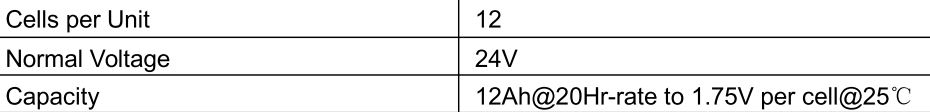
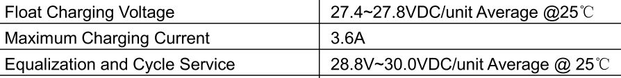
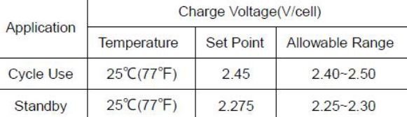
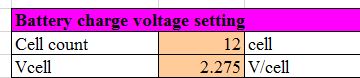
I am developing a control system with battery charging control from solar panel. It is a lead-acid 24V 12Ahr battery with 12 cells. My plan to use BQ24650 and BQ34110 combining together to control charging and measure coulomb counter, voltage and temperature.

From TI website and datasheet, I cannot find below questions' answer:
1. Deos BQ24650 support 12 cells lead-acid battery charging control? In TI website, it mentions up to 6 cells.
2. When will BQ24650 put on market? Does it support 12 Cells lead-acid battery?
3. Does BQ34Z100-G1 support 12 cells lead-acid battery? Does it have coulomb counter? Can it combine with BQ24650 for battery charging control?

Thanks,
Gansheng

  • Gensheng,

    1). If you are charging up to 24V,  the bq24650 is capable of this. The device will enter sleep mode when Vbat is greater than or equal to VCC- 300mV or so. Up until that point, the charger will charge (all other conditions being satisfied). Just make sure you have the solar capacity to maintain that voltage for all weather conditions you intend to charge.

    The bq24650 was originally intended to be a Li-Ion based charger. The max charging voltage is ~4.2 V/cell for Li-Ion, giving the bq24650 the ability to charge at most 6 series cells. With Lead-Acid, the bulk voltage is ~2 V per cell, giving it the ability to charge more cells in series.

    2) The bq24650 has been available to the market for quite some time. You should be able to charge a 24V Lead acid battery (the equivalent of 12 series cells). I would not try to charge much higher, as the float charge voltage will be slightly higher than 24V probably.

    3) I cannot speak to the gauge functionality for this  application, as I am mostly unfamiliar with them (they are actually a separate group within the company). You may want to head over to the gauge forum, and they will be able to give you a much better answer than I am capable of. In general, the gauge should be able to work with the bq24650. I am not sure about 12S Lead Acid, though.


  • Hi Gansheng,

    You can also look at the app note www.ti.com/.../slva437a.pdf which explains how to implement pulse charging and temperature compensation for a Lead Acid application.

    Regards,
    Steven
  • Thanks for your answer. In item #2, I tried to ask about BQ34110 bringing to market timeline for it is in Preview status on TI website.

    When I develop BQ24650 for charging control, is it possible to use WEBENCH design under battery management, or Battery Management Studio (bqStudio) Software, or other assistant tool?
  • Gansheng,

    Unfortunately, I don't have the contacts to find out the RTM date for the bq34110. There may be someone in the gauge forum that can tell you that, but as a lowly engineer in battery chargers I am not told these things :)

    As far as developmental tools, the battery charger IC's are very complicated to model, so there is no WEBENCH for battery chargers (as far as I know).

    The bq24650 is a standalone device (everything is R-C settable). bqStudio is used to communicate via SMBUS/I2C to host controlled chargers during the prototyping stage.

    If you follow this link: www.ti.com/.../toolssoftware
    There are tools that will help you calculate the components you will need for your circuit. You can also post any questions here and I will be able to help guide you through the process.
  • Hi David,

    I have a few question:
    1. How to choose Vmppset? In BQ24650 datasheet, there is a formula for calculation of Vmppset, but it is based on R3 and R4. So how to choose R3 and R4? In the datasheet example, it chose 18V, but I do not understand how/why is that.

    2. How to choose 103AT NTC? There is a thermistor connected to TS pin. But in datasheet, I do not see how to choose its value.

    3. In TI's website, there is mppTrackingWithBQ24650AndNTCthermistor.xls to calcuate NTC, but its connection is different from datasheet one. Would you think which one is better?

    Thanks,
    Gansheng
  • Gansheng,

    1) Vmppset is typically specified by the manufacturer of the solar panel. If you are unfamiliar with it, you may find this app note interesting: http://www.ti.com/lit/an/slua586a/slua586a.pdf.

    This app note explains maximum power point tracking as well as how to use the spreadsheet. The NTC in the spreadsheet is actually for changing MPPSET with solar panel temperature. For now, you probably do not need this functionality.

    If you cannot find a MPP value in the solar panel datasheet, a good rule of thumb is 80% of the open circuit voltage (ie Vmppset = 8V for a 10V solar panel). To choose R3 and R4, use the equation:

    Vmppset = 1.2(1+R3/R4)

    Solving this will give you an R3/R4 ratio, then you have the freedom to choose the resistor values to satisfy the ratio. Using larger resistor values will give you a smaller current "stolen" from the power supply.

    2) Choosing the correct thermistor can be tricky. You could start with this one:http://www.mouser.com/ProductDetail/Semitec/103AT-2/?qs=wgO0AD0o1vvcDzsKguD%252bew%3D%3D

    This one is a nominal 10k Ohm thermistor. After choosing this, you look at the table containing information for Resistance vs Temp - this is found in the thermistor datasheet:

    From there, you can determine what you want for your "hot" temperature and "cold" temperature. Find the resistance that matches those temperatures in the 103AT column. From there, I would recommend plugging in those values to the bq46xx calculation tool spreadsheet, and it will tell you the correct values for the TS pin voltage divider.

    3) For now, I would not use an NTC for the MPPSET. I think that the circuit given in the datasheet is a good starting point. I would only use a thermistor for the TS pin.

  • David,

    BQ24650's working voltage is from 5-28, and it was said that the max voltage could be 30V. My solar panel is 24V system. So its maximum power voltage is above 30V. Would you have any charge controller recommended?

    Thanks,
    Gansheng
  • Gansheng,

    If your solar panel is 24V open circuit, I do not think it is possible for you MPP to be higher than that. If your solar panel is 24V, MPP will probably be between 18-20V. The bq24650 should be able to handle this.
  • David,

    Based on 24V solar panel electrical spec, its open circuit voltage =44.6V, Maximum power voltage = 36.0V , and nominal voltage = 24V.

    Regards,
    Gansheng
  • Hi,

    1. Since MPPSET is regulated to 1.2V, may I use D/A to set it to 1.2V from MCU? That would be easier and more accurate to control than using NTC. 

    2. I have a solar panel, spec as below:

    The battery spec:


    How would you think to use the solar panel to charge the battery with BQ24650?

    3. In the battery spec, it specified the charging set point, but how to use them to BQ24650 setting? 

    4. From TI website, I download a spreadsheet: bq246xx Calculation Tool V1.5 (Rev. D) -sluc175d. For Vcell, should I use the Set Point for Cycle Use or Standby?

    Thank you,

    Gansheng

  • In BQ24650 datasheet, for temperature qualification 103AT NTC thermistor is on battery pack, but not mounted on PCB. So I need to set up connector to connect this thermistor to PCB. Is there any requirement for the connection? I do not see the battery pack coming with 103AT. Where is the good location for me to mount 103AT on the battery?

    Thanks,

    Gansheng

  • Gansheng,

    You are correct - the thermistor should be as close as possible to whatever it is monitoring. There is no real requirement that I am aware of - it just needs to be as close as possible, and have a good electrical connection. As far as a good location - just make sure they share a ground, the thermistor is physically close to the battery, and you can easily access all the terminals.
  • Hi,

    In BQ24650 datasheet, it has thermistor connected to TS pin for temperature qualification.

    In the document "Using the bq24650 to Charge a Sealed, Lead-Acid Battery-slva437a", there is no this thermistor. But there is one attached to the output battery pack, and connected to VFB pin. as below:

    How would you these two different configuration for my 24V lead acid battery? and why/what does make it different? 

    Thanks,

    Gansheng

  • Another question also related to document "Using the bq24650 to Charge a Sealed, Lead-Acid Battery-slva437a". In this document, when it calculated current sensor resistor, it said that "It is generally recommended to charge lead-acid cells between 0.1-0.3 times the batterys maximum current rating during CC charging." But in BQ24650 datasheet, it directly use charging current for fomula: Rsr = (40 mV)/(Icharge). Which one would you think is better for lead-acid battery?

    Thanks,
    Gansheng
  • In regards to the thermistor question:

    They are two different thermistors intended for two different purposes. In the top image, the thermistor monitors battery temp and will keep charging as long as the temp is in a safe range.

    For the bottom image: That thermistor is optional i believe. The purpose of that thermistor is to adjust the "float" charge voltage with temperature. You could add this to squeeze a bit more lifetime/performance out of your battery, but it may not be worth the hassle.
  • In regards to your charging current question: It is better to use 0.1-0.3*C (C being the charge rate/capacity) for lead acid. The datasheet equation just tells you how to pick your sense resistor value.

    So, if you are wanting to charge a 10 AH lead acid battery, it is safe to "fast charge" with between 1 and 3 Amps. If we use the middle ground of 2 Amps, this gives a sense resistor value of 0.04 Volts /2 Amps = 0.02 Ohms.