This thread has been locked.

If you have a related question, please click the "Ask a related question" button in the top right corner. The newly created question will be automatically linked to this question.

TPS650944 I2C access with USB2ANY

Other Parts Discussed in Thread: USB2ANY

Hi,


My customer would like to validate TPS650944 on their board with CPU removed. Therefore, they connect all the control signals (including PMICEN, SLP_xxx……etc.) to 3.3V directly which are originally from CPU.  With such setting, their cold boot sequence can be executed well until PCH_PWROK rises after VSYS insertion.  Therefore, the last thing is to enable BUCK2(VCCGI) through BUCK2CTRL register. 


Since they don’t have CPU on board, they need other way to access PMIC I2C. I provided a USB2ANY box (the same one used with TPS650830EVM) to them for such test.


With this box connected to their board, their test set-up is as below.

  • Remove the external pull-up resistors to 1.8V on DATA and CLK pins of TPS650944. Since CPU is removed from the board, DATA and CLK pins are unconnected on this board now.

  • Connect DATA/CLK/GND from their board to the corresponding locations on USB2ANY connectors.

Since there’s pull-up to 3.3V on DATA/CLK within USB2ANY box, we expect it can work well with their board without external pull-up resistors.


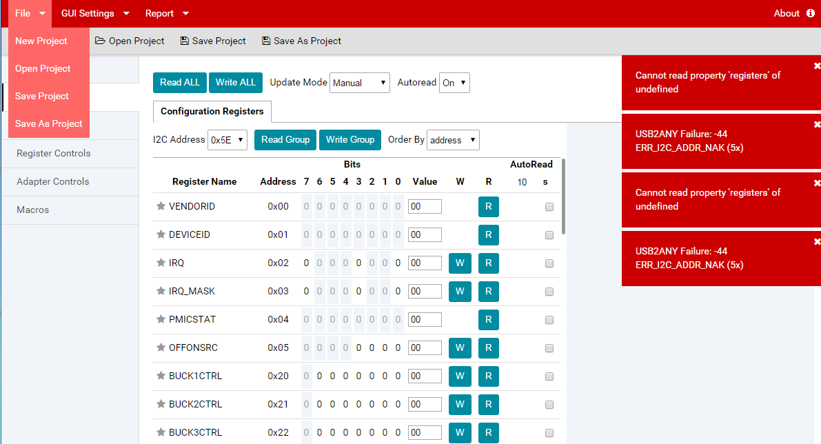
After several trials, we still not able to read/write register on their board from USB2ANY. When we click either read or write, error message like below will appear.


Meanwhile, with exactly the same set-up, another engineer can access TPS650944 register on another board (a different project but with almost the same schematics design.) Besides, the same laptop with the same IPG GUI set-up can work well with TI’s TPS6094x EVM from my customer.  Before CPU is removed from the board, the CPU works well with the PMIC as well.


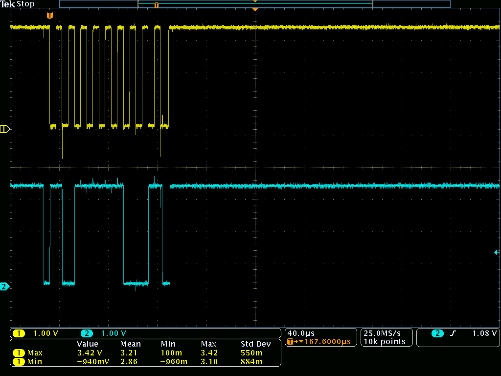
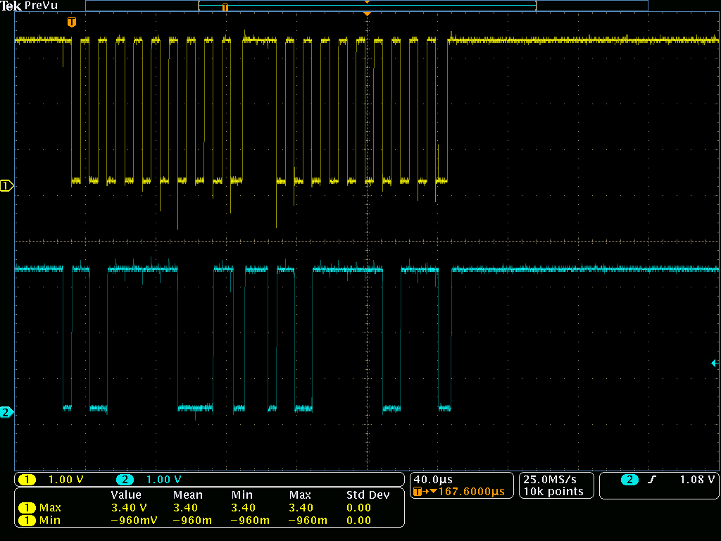
I have no idea why it’s not working on their board, even I use my own laptop. (IPG GUI and USB2ANY are both updated versions.)  We capture the waveforms when we read and write BUCK1CTRL register as below.  It seems there’s no ACK from the PMIC?


BUCK1CTRL Write:


BUCK1CTRL Read:


We would need your help to clarify what could be the root cause.

  • Should they implement an external pull-up to 3.3V on their board?

  • Do you think the negative voltage on CLK waveform is an issue for this?

  • 0x5E should be correct I2C address, right?


Please let us know your ideas.


Thanks!


Antony

  • Hi Antony,

    In the screenshot we can see that I2C command appears to be going out properly (0b101110 = slave address 0x5E, next is always '0' for read or write) but that the NACK is not received (active low acknowledge signal from PMIC).

    They should be able to rely on the pull-ups with the USB2ANY. It appears to be working well according to the scope shots. I don't think negative voltage on CLK waveform is a concern. 0x5E is the correct address.

    My first thought would be that perhaps SCL and SDA are being switched, but I am guessing you have already tried swapping them as that is usually the first thing I try.

    Where are the scope shots taken? Can they take them at the pins of the PMIC to ensure that signal is properly reaching the PMIC? Are the output rails of the PMIC stable? If they are resetting it could explain why there is no ACK.
  • Hi Kevin,

    THere's some new update from customer as below.

    Now when they tried to configure BUCK2CTRL to 0x33, they found sometimes the "changes not written" in the GUI as shown below could be "red light" and sometimes be "green light".  But for either case, there's a possibility that BUCK2 could be enabled to the right voltage.  But, the voltage can only lasts for 10 seconds.  What is your comment now?

    Thanks!

    Antony

  • Hi Antony,

    Can they read the PWR_FLT_STAT registers to see if any rails are having a power fault? How about OFFONSRC register?

    One item to note is that for BUCK1 (VNN) and BUCK2 (VCCGI), the feedback feeds directly into the processor. If they don't have an alternate connection, then the rails have no connection to their output. For many customer designs, they include a local feedback point connected via a resistor (49.9 ohm typically). If this is not installed or present, they won't be able to properly regulate.

    If they are seeing BUCK2 turn off, it would suggest the PMIC is resetting. We need to identify the cause of the reset. It would also explain why sometimes the I2C read/write isn't working (it won't work during an emergency shutdown). 

  • Hi Kevin,

    In case BUCK1 FB trace is not implemented, will cold boot sequence continues after the step of "BUCK1 enable"?

    Do you mean that PMIC will emergency shutdown if either BUCK1/BUCK2 FB is not implemented? Since the power up condition (PMICEN and all the control signals are valid), I think PMIC will reset repeatedly, right?

    From above, when emergency shudown, it seems everything will be turned off, right? (Based on Figure 6-12. Emergency Shutdown Sequence) If so, are we still able to read PWR_FLT_STAT and OFFONSRC register?

    Thanks!

    Antony
  • Hi Antony,

    BUCK1 (VNN) is supposed to start first, however because it transitions from A rail to S rail, BUCK4 (V1P8A) cannot depend on BUCK1 PG since BUCK1 will be disabled in sleep, while V1P8A remains on. As such, if BUCK1 fails, BUCK4 and following rails will still boot. After 10 ms (time during which power fault is masked during start-up), the PMIC will enter emergency shutdown since BUCK1 power fault occurs.

    Yes, PMIC will emergency shutdown if BUCK1 FB is not implemented unless they mask the power fault prior to setting PMICEN high. If they enable BUCK2 without masking power fault on BUCK2 and BUCK2 FB is not connected, then it will power fault and force reset as well.

    You are correct that if PMICEN is forced high, the PMIC will power back on if all control rails (PMICEN for example) are tied high after the emergency shutdown.

    They should be able to read the registers if they set PMICEN low, or if the I2C falls between faults, then they can read even with PMICEN tied high, as long as the I2C is not interrupted by a power fault.

    The state of the PWR_FLT_STAT and OFFONSRC registers persist through an emergency shutdown OTP reset.
  • Hi Kevin,

    Do you mean PWR_FLT_STAT and OFFONSRC registers values would be kept as long as VSYS is not removed and no one clear them?

    In case a emergency shutdown happened as we assume, do you mean you want to keep PMICEN low to prevent PMIC start again so that we can read I2C in a stable condition (instead of reset repeatedly?)

    Thanks!

    Antony
  • Hi Antony,

    You are correct on both questions.

  • Hi kevin,

    We have further test result now as below. 

    Currently after BUCK2 is enabled through IPG GUI, it can reach the correct value, but will drop some time later.  (It coud be 10sec later or even 1 min later.)  I'm asking customer to probe both BUCK2 and BUCK1 from the beginning.  After BUCK1 is enabled, it always keep high even after BUCK2 is off unexpectedly as mentioned above.  So, it is not an emergency shutdown, right?

    After BUCK2 is off unexepectedly, ask them to dump the registers (as attached) and I found BUCK4_PWRFLT bit is high.  I'm waiting for their measurement result on BUCK4 now during the test.  Before that, can you provide your comments accordingly?

    Thanks a lot!

    Antony

    regdump.txt
    Fullscreen
    1
    2
    3
    4
    5
    6
    7
    8
    9
    10
    11
    12
    13
    14
    15
    16
    17
    18
    19
    20
    21
    22
    23
    24
    25
    26
    27
    28
    29
    30
    31
    32
    33
    34
    35
    36
    RegAddr Value
    00 22
    01 0C
    02 88
    03 FF
    04 00
    05 06
    20 38
    21 00
    22 11
    25 0C
    26 0C
    27 00
    40 55
    41 55
    42 05
    43 07
    91 00
    94 2F
    96 4B
    98 3D
    9A 00
    9B 00
    9C 07
    9E 00
    9F 68
    A1 20
    A2 C0
    A3 37
    AD 61
    AE 69
    B0 3F
    B1 60
    B2 08
    B3 00
    B5 00
    XXXXXXXXXXXXXXXXXXXXXXXXXXXXXXXXXXXXXXXXXXXXXXXXXX

  • Hi Kevin,

    After the issue happen, I see BUBCK2CTRL becomes 0x00 automatically. Do you have any idea?

    Thanks!

    Antony
  • Hi Antony,

    If BUCK4 has a power fault, the part will have an emergency shutdown and re-load the default settings (i.e. BUCK2CTRL set to 0x00). If PMICEN is high after emergency shutdown, the part will start back up. BUCK1 will only be off for less than a millisecond before it is re-enabled, so the Vout will likely only show a small dip, if anything.

    It sounds like something on their V1P8A rail is having issues with the processor removed. They will need to isolate what on the V1P8A is causing the power fault.