This thread has been locked.

If you have a related question, please click the "Ask a related question" button in the top right corner. The newly created question will be automatically linked to this question.

TPS65094: TPS650944 VNN, VCCRAM, VCCGI no power

Part Number: TPS65094

Hi expert,

Customer has an issue on their project. They found out there are three power rails fail to power on but other rails are all okay. As we know, TPS650944 should power on every power rail follow the power sequence. But VNN is not okay and other rails powered on is not reasonable. Would you kindly help to suggest any clue to figure out this question? Thanks a lot!!

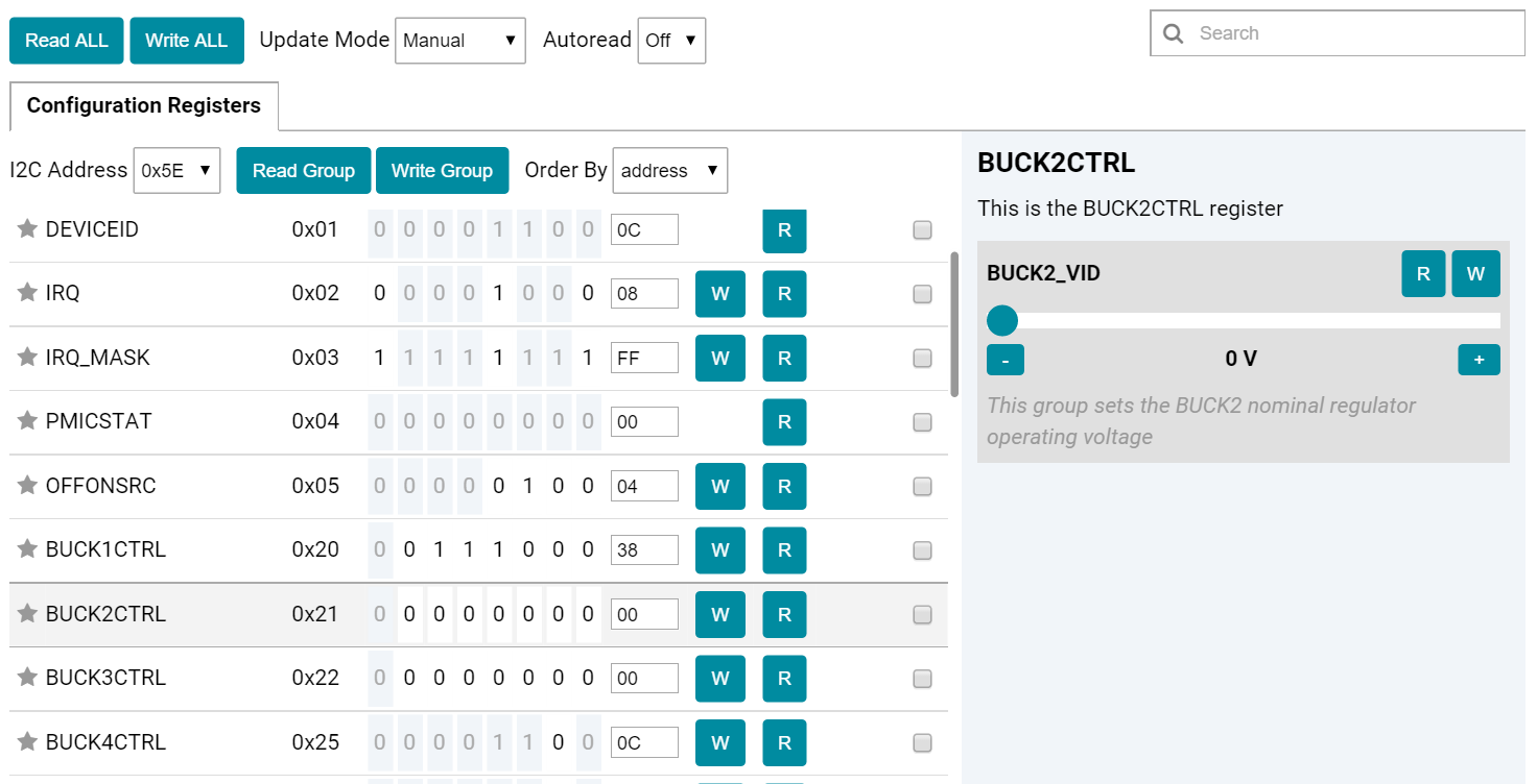
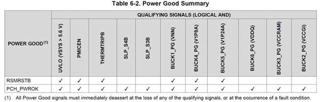
 No power : VNN, VCCRAM, VCCGI,

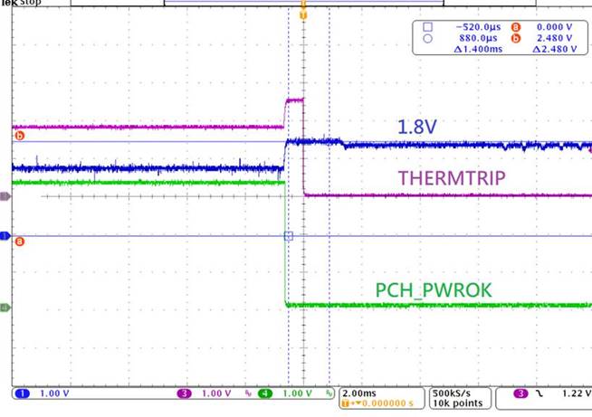
THERMTRIPB is keep 2V.

Best regards,

Ann Lien

  • other rails are all okay? BUCK4 ,BUCK5,RSMRSTB ?
  • Hi expert,

    We tested with real board and power are all okay besides VNN 0.05V/VCCRAM 0V/VCCGI 0V. And we use GUI to capture the data and found out PGOOD is high for BUCK1 but VNN is only 0.05V, picture is shown below. And also, RSMRSTB/PCH_PWROK are both high.

    We compared good board and fail board and found out we can adjust Buck4 in good board but cannot in fail board. customer also mentioned Apollo lake has some compatible issue with PMIC IC. I don't know if these two things are related.

    Could you kindly help to suggest any clue to debug?Thanks a lot!!

    Best regards,

    Ann Lien

  • Hi Ann,

    I have assigned this to our device expert.

    Reviewing though, have you checked the voltage on SLP_S0B? The status you describe sounds like Connected Standby. In Connected Standby (see Figure 6-9 in the datasheet), BUCK1 (VNN) is set to 0 V, while BUCK2 (VCCGI) and BUCK3 (VCCRAM) are disabled. That would explain why the PG is '1' for BUCK1. Note that VCCGI (BUCK2) VID is written by the processor, so even when enabled, it is 0 V until the processor provides the appropriate VCCGI voltage (varies by processor).

    There are no compatibility issues between APL SoC and TPS65094 family.
  • Hi Kevin,

    Thanks for reply!!

    Customer has a question on PWR_OK. As we know, CPU would transmit VCCGI VID to PMIC then VCCGI would power on. But from below table, PWROK need VCCGI OK then PWROK will assert. Could you kindly help us to explain it?

    And also, do you have any clue that 1.8V rail would be change to 2.5V? We found out there is one fail board that 1.8V will change to 2.5V without any I2C command. And we cannot see any command that we could let 1.8V rail change to 2.5V since the maximum is 1.8V for VID.

    Would you kindly help on this case? Thanks a lot!!

    Best regards,

    Ann Lien

  • Ann,

    You are right that PCH_PWROK monitors BUCK2_PG, however that does not mean that the processor needs to set the BUCK2 voltage before PCH_PWROK goes high. The BUCK2 voltage is initially set to 0V, so before the processor sets a new BUCK2 voltage PCH_PWROK will have a valid BUCK2_PG signal. After the processor sets the voltage PCH_PWROK will continue to monitor the BUCK2_PG signal so that if it drops from that new set voltage PCH_PWROK will go low.

    As for this voltage increase on the 1.8V rail, this should not happen without any I2C command setting this rail to 2.5V, which is possible. If you look at table 6-4 in the datasheet this rail can be set as high as 3.575V.

    Please let me know if you get any updates on the status of the SLP_S0B signal.
  • Ann,

    Any updates on the status of the SLP_S0B signal?
  • Hi Nick,

    Thanks for detail reply!! Will let customer check SLP_S0B signal and give back to you.

    Best regards,

    Ann Lien