This thread has been locked.

If you have a related question, please click the "Ask a related question" button in the top right corner. The newly created question will be automatically linked to this question.

BQ24610: BQ24610 burned after first charge cycle

Part Number: BQ24610
Other Parts Discussed in Thread: CSD18504Q5A

Hello,
my customer have a strange issue.
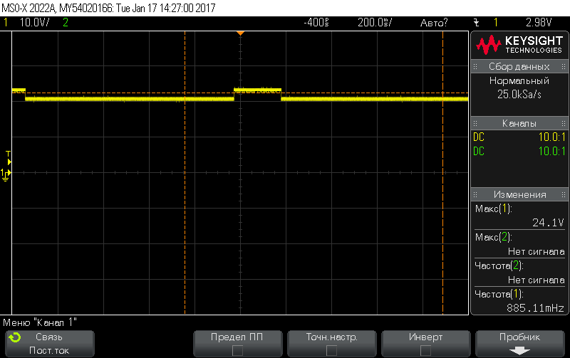
After first charge cycle High side driver (HIDRV) has permanent open, when low side driver (LODRV) has switching.
As result BQ24610 getting hot until burned. All other components in design are working good after it. Thermal protection can't prevent it.

While first charge cycle all's going good - controller working by charge curve and all protection system are working too - connection/disconnection of battery, OCP.
But when charge complete High side switch are going in permanent open mode.
It's need to be pointed that they use scheme with some change that recommend design.  See ChSheet1.pdf.
There are main difference - VS in place of Q3 (BATDRV). I'm not sure that It correct replacement and should working, but in the same time I can't found mention that it's wrong.

Customer already burned some samples of BQ24610 (5 pcs.).
What's wrong?

Best regards

  • Hi Vladimir,

    Is there a system connected to VD3? If not, I don't think it is needed if you are only using the bq24610 to charge a battery. Also, is there a schematic with the values to each component? I also want to see the voltage rating for each capacitor.

    If you can, send me the charge cycle curves if any, and try to use an oscilloscope to look at VCC, SRN, REGN and HIDRV when charging is complete. See if there is anything odd on the waveform.

    Regards,
    Steven
  • Hello Steven,

     
    You can see component and description when left mouse click for each component.
    It's need to be pointed that there are using a Russian description. For example C6 - 1206-Y5V-50В-1мкФ±20%, where 50В = 50V, 1мкФ = 1 uF.
    As I can see all's good there.

    I'll asking for oscilloscopes. I'll come back when got it.

  • There are oscillograms without battery.

    VCC

    SNR

    HIDRV

    REGN


    When battery is connected BQ24610 working in short circuit mode (only low side switch are operating).

    Vin = 25V, Battery - 21V @ 1.6A.

  • Vladimir,

    On the schematic I found a few components that need to change:
    1. C15 change to 22pF
    2. C16 remove
    3. R16 to 100kohm
    4. R15 to 800kohm
    5. Remove VD3 if system is not attached
    6. C11, C12, C13 are meant to be placed close to IC pins
    7. Split C14 into 1x1uF + 2x10uF, with 1uF close to R14
    8. Split C5 into 1x1uF + 2x10uF, with 1uF close to VT3 drain
    9. Use FET with less Qg, I recommend using CSD18504Q5A for both HIDRV and LODRV

    I think the problem here is that not only does the IC looks damaged, it would also seem that another component of the power stage may have gotten damaged. Please check the bootstrap cap, the bootstrap diode, the high side FET, the low side FET, input cap and output cap.

    In the scope shots looks like battery detection pulses, but also REGN should not have that waveform. It should always be stable 6V on REGN. See if you can desolder the IC and measure continuity on REGN with other pins to see if it is shorted.

    One question: How many cells and how much voltage per cell on this application? What would be the application of this design?

    Thanks,
    Steven