A related question is a question created from another question. When the related question is created, it will be automatically linked to the original question.
If you have a related question, please click the "Ask a related question" button in the top right corner. The newly created question will be automatically linked to this question.
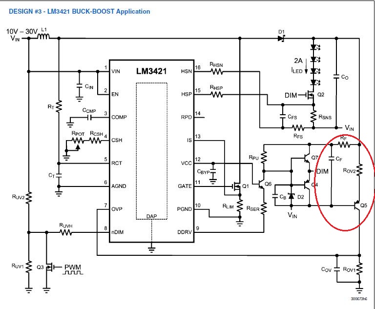
There are actually two circuits circled. The Rf and Cf simply add some delay to the turn on/off of the dimming FET Q2. Q5 works in conjunction with Rov1/2 to level shift the OVP and cancel out the input voltage. That way you are only measuring the output voltage rather than Vin + Vout for your over-voltage protection.
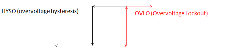
If the output voltage rises to the 40V threshold the LM3421 will stop switching. When it stops switching the output capacitor will discharge. It will begin switching again when the output voltage falls to 30V (10V hysteresis) where it will begin switching again. It will cycle on/off like this until whatever fault is causing OVLO (usually an open LED string) is corrected.