This thread has been locked.

If you have a related question, please click the "Ask a related question" button in the top right corner. The newly created question will be automatically linked to this question.

TPS25923: TPS259231: The behavior of current limit

Part Number: TPS25923

Hello,
I have a question about TPS259231.

My customer is checking the operation by the mounting to a prototype.
Please give me comment about the following behavior.

■The condition of TPS259231
VIN-pin : 6.0V input from external power supply
ILIM-pin : 45.3kohm (current limit setting is 2.1A(typ))
OUT-pin : Load electric current adjustment by the electronic load connection
dV/dT-pin : open
BFET-pin : open

■About the waveform of output voltage and output current
(Ch1: Input voltage,  Ch2: Output voltage,  Ch4: Output current)

↑  Load electric current setting by the electronic load: 1.5A

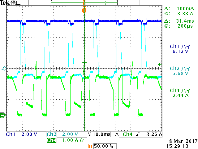
↑  Load electric current setting by the electronic load: 2.5A

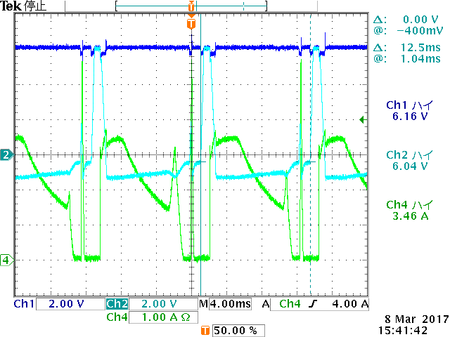
↑  Load electric current setting by the electronic load: 4.0A


When the settings of load electric current are 2.5A and 4.0A, the following behavior is observed.
(When the setting of load electric current is 1.5A, the following behavior is not observed.)

・Output current : Cyclic ON/OFF behavior
  Is it repetition behavior of the output OFF → return by the current limit operation ?

・Output voltage :
  After output voltage dropped by increasing electric current, output voltage becomes minus voltage.

Are these behavior correct?
Please teach me the reason about these behavior.

Regards,
Dice-K

  • Hi Dice,

    When the load current is above the set current limit 2.1A, the device operates in current regulation mode and eventually turns OFF due to thermal shutdown. Since, TPS259231 is auto-retry version, we expect repetitive behavior at the output.
    Can you let me know which mode the electronic load is set? CC mode or CR mode? what is the make/manufacturer of electronic load?

    Regards,
    Rakesh
  • Hello Rakesh,
    Thank you for your reply.

    The electronic load is CC mode.
    The maker is KIKUSUI.
    The model is PLZ164WA.

    www.kikusui.co.jp/.../detail.php

    Is this information useful?

    Best regards,
    Dice-K
  • Hi Dice,

    Thanks for the details.
    Please use e-Load in CR mode. When the eFuse device reaches current limit, the device acts as a current source. If an electronic load is used for testing in CC mode, which turns out to be placing two current sources in series in the network. This pulls down the output voltage and the behavior depends on the electronic load.

    Best Regards,
    Rakesh
  • Hello Rakesh,
    Thank you for your reply.

    My customer confirmed it with electronic load as CR mode.
    When the setting of load current is 2.5A, he confirmed the behavior that the current limit is 2.1A.

    At the time of the current limit, does ON resistance grow large by Gate control of the internal FET?
    As a result, does the output voltage drop?
    Is this correct behavior?

    Best regards,
    Dice-K
  • Hi Dice,

    Yes, what you explained is the correct behavior. In current limit mode, the current loop controls the FET GATE voltage and increases the ON resistance of the FET to regulate the output current (equal to current limit setting). In this process, the output voltage droops.

    Regards,
    Rakesh