This thread has been locked.

If you have a related question, please click the "Ask a related question" button in the top right corner. The newly created question will be automatically linked to this question.

BQ24072T: BQ24072T is hot

Part Number: BQ24072T
Other Parts Discussed in Thread: TPS61252, , BQ24380

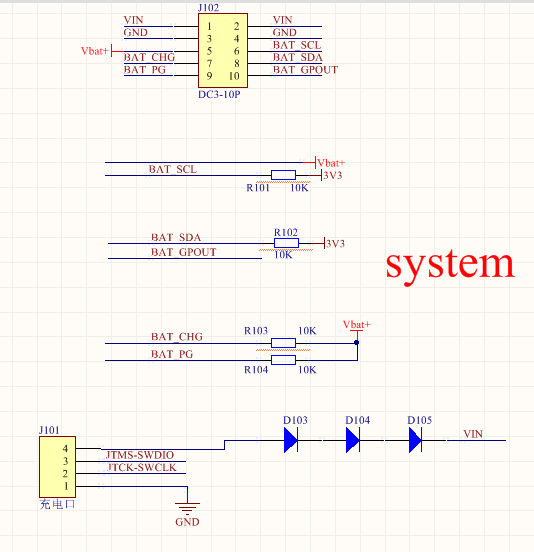
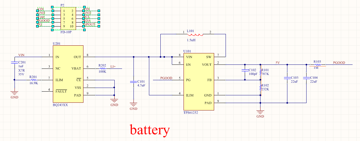
BQ24072T  is used as a charger  in my project。A boost chip TPS61252 is added before BQ24072T ,because input voltage less than 4V。The following Figure shows my circuit. BQ24072T works in USB500 mode(EN1= 1,EN2=0),the charge current is 300mA(RISET = 3K).

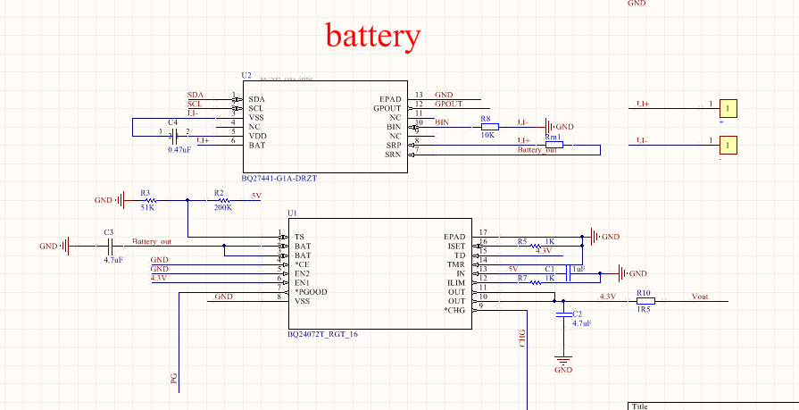
Usually BQ24072T works normally,but sometimes it is hot,when the battery discharge。At this time, discharge current is 627mA,IN (PIN13) is 0.4V,TS is 0.5V,ISET is 0.6V,PG is 0V;Under normal condition,they should be 0 except PG is high 。

What is the reason for my problem?

  • Hello,

    Do you test these pins' voltage when work normally(not hot condition), what's the voltage is?

    Regards

  • Under normal condition,,IN (PIN13)is 0V,TS is 0V,ISET is 0V,PG is 3.7V(battery voltage)
    In addition, after the end of the battery discharge, part of the chip can work, and some can not work。After replace the battery, PG of the chip what can not work appear two cases,one is 3.7V,the other is 0V。
    I think whether or not EMC is reason.
    is BQ24072T an industrial product?
  • Hello,

    it could be used at industry, and work normally generally. you need to find the reason in your application environment if it is damaged.

    Regards

  • Hello,
    I want to find the reason,but i don't know how to find the reason.
    It is currently tested under laboratory conditions,and no more environmental factors have been added。

    According to the test, I think the charging part is damaged。Is it possible to damage the chip because of the wrong pin connection,such as a pin(TD,EN) that requires a pull-up resistor, but is directly connected to the VIN or OUT;EN should be connected to the IN, but connected to the out。

    In addition, do we need to replace the chip?Previously used chips do not have this problem,such as BQ24032, VA7205 made in China,
  • Today,i found the power dissipation of the chip that heated once is high,when battary discharge。the current is 20~40mA,normally uA level. Remove other chips,nothing change.
  • Hello,

    You could find the BQ24072T's datasheet and EVM guides at here: http://www.ti.com/sitesearch/docs/universalsearch.tsp?searchTerm=24072t#linkId=1&oldSearch=1. It will be helpful, recommend refer to it to design the SCH.   

    Regards

  • hello!
    I have read the datasheet ,user's guides and application reports many times。I don't found incorrect connnection。

    1.EVM guide(slvu274e) says “Resisitors,in dotted box,typically not needed in a design but used here toassist in evaluation of the ic or protect the evm from incorrect input connection". these pins are TD,TMR ,CE,EN. The pull-down resistors are not needed 。

    Is my idea right?

    2.EN is connected to IN in the EVM guide, but in a Application Report(sluu 332 “Power-Path Li-Ion Charger Selection”),EN is connected to OUT。I don't know the different of the two connections。when battery discharges,Whether the latter will cause Q1 or anything anomaly。

    how to connect EN?

    3.In addition,when only connect battery,IN is 2.2V。Connected IN to 5.4V,PG is high,Normal is low。I think negative voltage causes internal FET damage。External power supply cannot be connected to internal device。

    4. BQ24380 are charger front-end IC designed to provide protection to Li-ion batteries from failures of thecharging circuit,
    Can BQ24380 be used as ESD protection chip?

    5. If negative voltage is reason,Are there solutions?
    I have two ways。one ,don't used internal power path management,instead of external FET or Fast Ideal Diodes chip。Refer to application report(SLUA376 ,Implementations of Battery Charger and Power-Path Management System Using bq2410x/11x/12x( bqSWITCHER ™ ))

    the other,add a ESD protection chip ,e.g. USB ESD protection chip。

  • Hello,

    1. TMR could be connected with GND directly to disable all safety timers. CE could be connected with GND directly to disable all safety timers to enable the battery charger. Also, EN2 could be connected with GND directly.

    But your EN2 and TD pin are connected with high logic level, that should use a 10K resistor, other than connect high voltage directly.

    2.EN pin, we just need give it a high or a low logic.

    3. when only connect battery, the FET between IN and OUT should be off, so 2.2V should be an issue, could you test your normal board to confirm it. I guess that the FET is damaged.

    You mean there is a negative voltage, why? do you connect a negative voltage at VIN? IC's VIN pin could not be connected with negative voltage at any time.

    Regards.
  • Hello,
    Now, I use BQ24075Q1, did not find such problems. The different is PIN15,BQ24075Q1 is SYSOFF connected GND,BQ24072T is TD connected to OUT directly。

    I also think that the TD pin is not directly connected to OUT。Next step ,TD will be connected OUT through a 10K resistor。Then whether can solve the problem。
  • Hello,

    Connect TD high to disable charger termination. Connect TD to VSS to enable charger termination.

    this pin is only about enable/disable about termination

  • Hello,
    Connect TD to OUT through a 10K resistor。 the problem is solved。
    Thank you for your answer!!