Hello Community,
Introduction/Background:
I'm currently working with PoE to design a Powered Device (PD). This PD is going to need class 4 power which contains 15.4 W from which 12.95 W will be available at the PD input (which is just about enough power). After passing through the classification process of the PD-interface chip, I'm planning to use DC/DC converters to get a lower usable voltage. I want to divide the input PoE power through 2 DC/DC converters to get 3.3V and 12-24V output.
Problem:
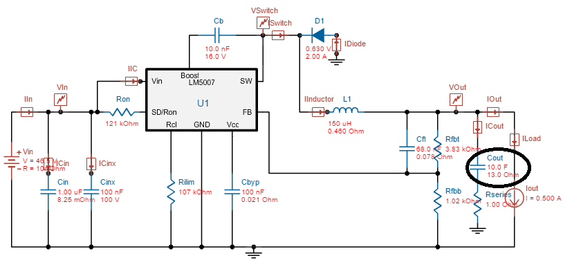
However for this thread I will be focusing on the first step which contains using the LM5007 to convert 36-57V to 12V. By following the datasheet I've calculated all values and decided to test this circuit out via a simulation and by building it on a breadbord. The new values that I calculated and used for simulation are presented in the schematic below: 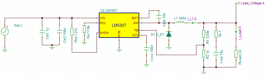
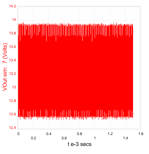
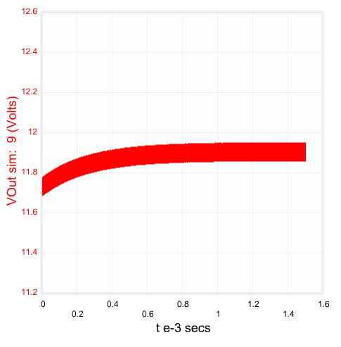
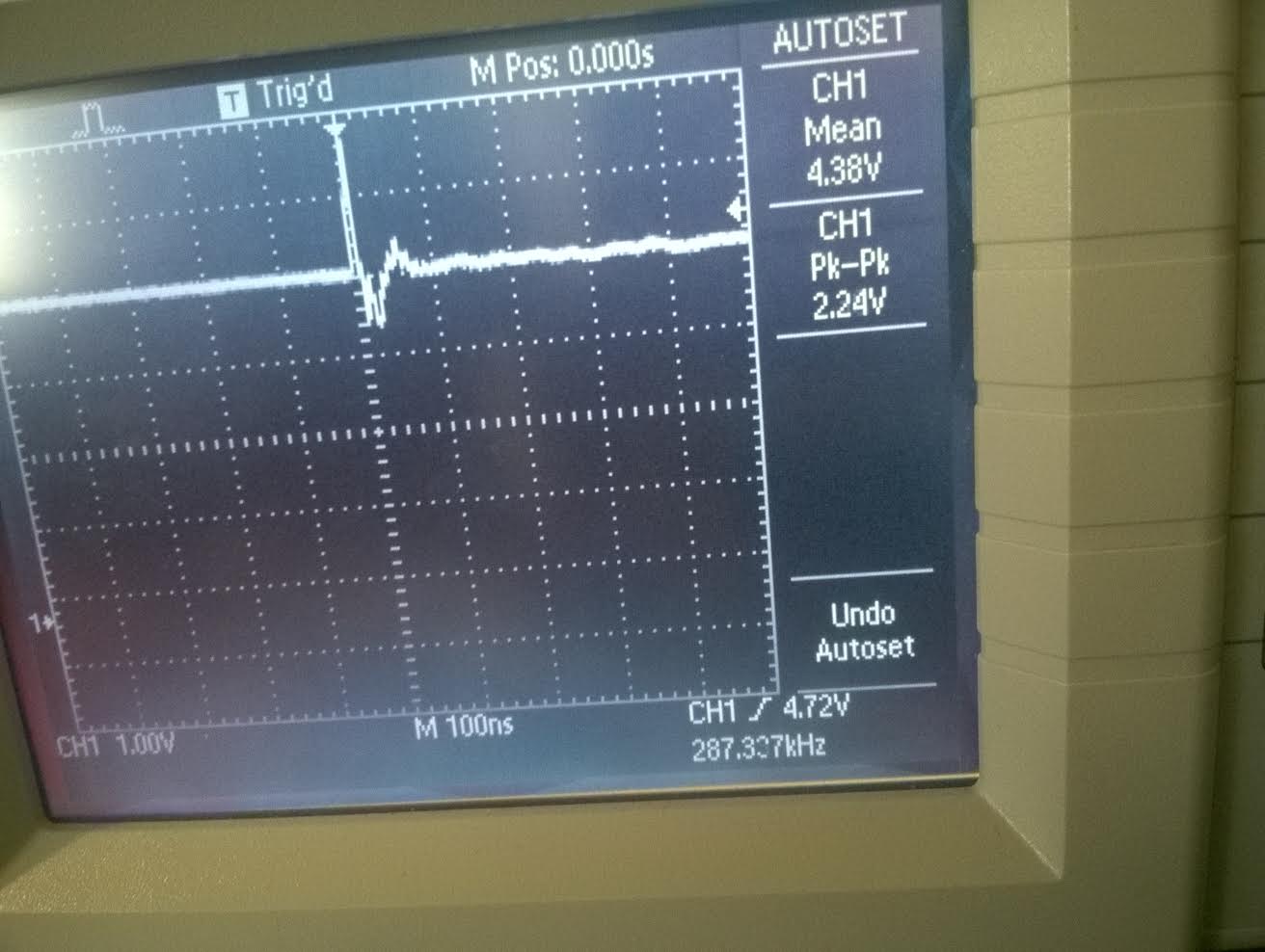
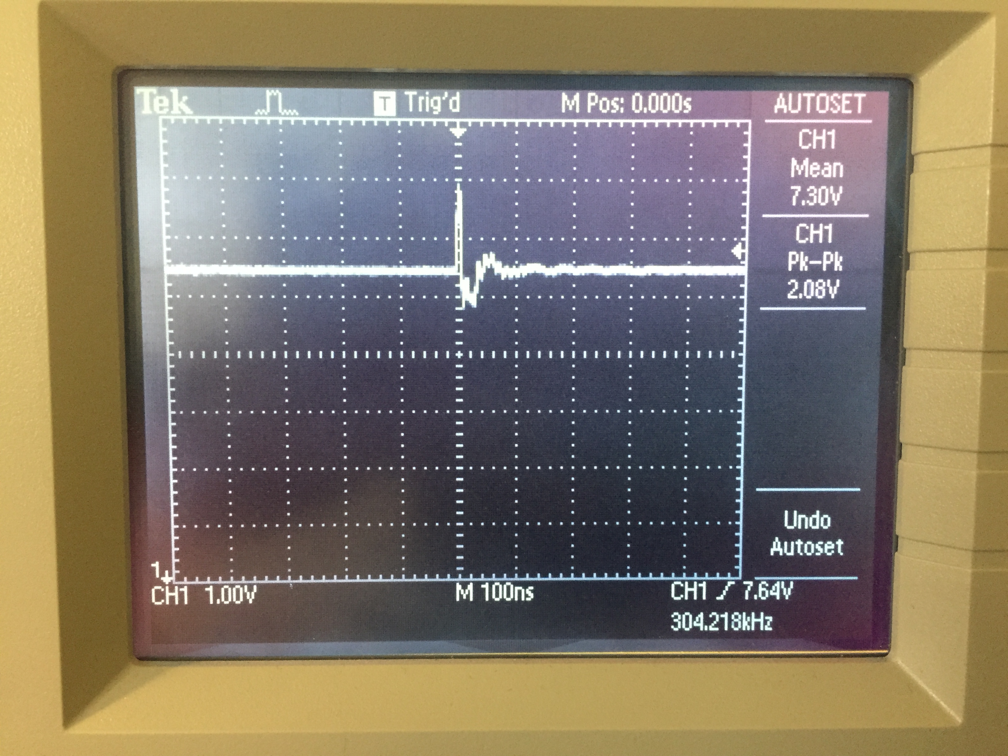
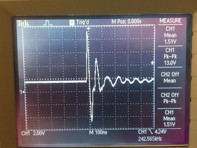
Using TINA this schematic simulates a correct output behaviour. However when I built this circuit on the breadbord (using a 100ohm resistor as load), I got a 1.51V over the Load resistor along with a Pk-Pk value of ~13V. (NOTE: Back then I used 243k for Ron and 8K for Rcl. After a couple of tests the first LM5007 chip started smoking and the second won't even respond anymore. So now I have calculated 121k for Ron and 110k for Rcl...and when I get another LM5007 soon I'll test it on the breadboard).
This is how it looked back then with the old values for Ron and Rcl along with 100ohm resistor as Load:
This happened even though the simulation gave a nice and steady output (including the old values for Ron and Rcl).
Solutions tried/pending:
1. I've rechecked my circuit on the breadbord many times and couldn't find an accidental short-connection which might have caused the first two Lm5007 to die suddenly.
2. I've tried using a bigger value for L1 and Cout to no avail
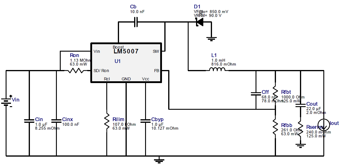
3. Tried WEBENCH suggested circuit, but didn't have the L1 of 1mH...so used my old 150uH instead. This still didn't work, but once I get the ordered parts I'll retry this circuit from WEBENCH.
Question:
Even though I've calculated new values for Ron and Rcl, I have little believe that I'll suddenly get a nice output signal on the scope. So I hereby ask if anyone knows what I might be doing wrong here?? I wish to have a steady output with a max of 200mV ripple and thus to reduce this giant mountain of a Peak voltage.
Let me know if more info is needed ( even though it looks like I might've spammed too much while describing my problem here).
Best Regards,
Flint