This thread has been locked.

If you have a related question, please click the "Ask a related question" button in the top right corner. The newly created question will be automatically linked to this question.

UCC25706: Problems with the power-on sequence

Part Number: UCC25706
Other Parts Discussed in Thread: TPS2829

Dear E2E team,

My customer has a problem described below.

Could you please help me with this issue and let me know if you have an idea from where this issue might come.

===================================================================

" I’m working with an old card that uses UCC25706D. We have problems with the power on sequence.

The situation is the following:

  • The power supply is designed so that the UCC25706D turns on when Vin of the DC/DC converter is 88Vdc.
  • In same cards, the IC does not turn on until Vin is higher than 120 or 130V.
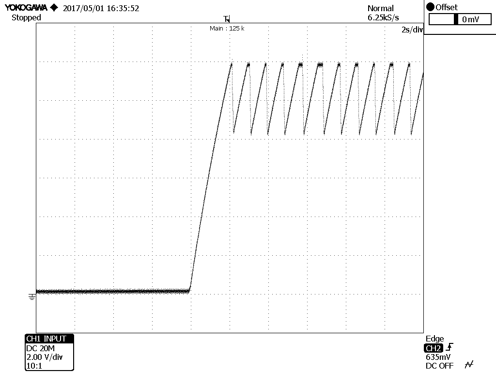
  • When the power on sequence fails it seems as if the current multiplier associated with Vff pin does not work properly. In fact the voltage is always 0 until the IC turns on. "

===================================================================

Thank you very much,

  • Can you share the schematic for this? Or at least the portion of the schematic related to the startup path for the IC?

    Can you share the calculation or design rationale for "designed so that the UCC25706D turns on when Vin of the DC/DC converter is 88Vdc"?


    If we get more details, we will be in a much better position to help you out.

    Thanks,
    Bernard
  • Dear Bernard:

    I send you the requested part of the schematic. But the fact is that, when we have the problem, we simply change the UCC27706D with a new one and the problem is solved. So we suspect that we have defective components.

    FC2361 _ PAGE1- F.pdf

  • Bilal, Cesar,

    On the boards that fail to start up at the expected 88 V dc, can you measure the VDD rail of the UCC25706 as it rises after AC input is applied? What is the rise-time and time constant? Where does the DC level settle out? Does it ever reach the 12-V start level?

    If you observe the same at 120-130 V dc where it does start successfully, what is different?

    And on a "good" board (or after the UCC25706 is replaced), what is different?

    What percentage of boards exhibit this issue? Was this issue always seen before, or is it a new issue, or has the failure rate increased recently?


    The path to charge VDD at startup is via R7/R10 to charge the 47-uF C20, and also 100-uF , effectively in parallel since R20 & R18 are much smaller value compared to R7/R10. This is approx. 20-s time constant.


    Taking an initial simplified analysis:
    - Vin =88 V dc
    - VDD start level for UCC25706 = 12.8 V max
    - Rstart = 136 k => available Icharge ~550 uA at this voltage level on VDD
    - VCC current for TPS2829 = 15 uA max. VDD start current for UCC25706 = 90 uA max. So there should be at least 450 uA charging current still available, so it should be able to charge Vdd > 12.8 V after enough time. But it could take a long time, several seconds.
    - Even though there is 3:1 ratio of the typ to max start current for the UCC25760, the current is still much smaller than the available charging current, so it should not have a significant impact.

    If we can see the VDD charging on a scope plot, this would helpful to try to identify the issue.


    Thanks,
    Bernard
  • Dear Bernard:

    I try to answer your questions:

    1) The rise time at Vdd for Vin=88V either in a good board or in a fail one is about 4s. I attached you scope plots. The first one is the Vdd voltage in a fail board.

    The second plot is a fail board in which we have changed the UCC25706D, so that it has been converted in a good board.

    The third plot is the Vdd plot in a fail board at 150Vin. As you can see, the UCC hasn't start-up properly. 

    Our production department has informed me that is a new issue, about a month ago. The failure rate is about 15% in the last production serie.

    I have done new test in a fail board that may be usefull for you:

    1) I have short circuit simultaneously R25 and R26 in a fail board. It hasn't had any effect in the minimum voltage at which the board powers on (about 150Vin)

    2) I have short circuit R10, and the board powers on at about 90V.

    Best regards

  • Cesar,

    Can you provide details of the lot numbers of the IC's with the issue. Best to include photos of the label on the reel, this will contain all the necessary lot trace info.

    If you prefer, you can email to me at bernardkeogh@ti.com


    Thanks,
    Bernard