This thread has been locked.

If you have a related question, please click the "Ask a related question" button in the top right corner. The newly created question will be automatically linked to this question.

PMP40025: Reg testing observation with PMP40025 Reference design

Part Number: PMP40025
Other Parts Discussed in Thread: UCC28730

Dear All,

one of my customer made PCB as per TI design#PMP40025, below are the steps followed and observations made, kindly need your valuable inputs.

                                         1)They externally supplied the controller UCC28730 to observe the switching pulses, But not observed. 

                                         2) Supplied UCC28730 from DC bus but no pulses can be observed, But there is fluctuation in VDD voltage after 21V which is the turn on thresold voltage. 


This is the initiation controller and I have to ensure whether its working and application in the circuit clearly. 

They started Testing twice and observed spark each time, following are observations,

                                                1) Increased AC voltage input through Auto transformer.

                                                2) First time - MOSFET gone when AC input was gradually increased.

                                                3) Second time: When AC input of about 98 V ac reached, there is a spark, Resistance R8, R11 & R12 are burnt, and transistor Q4 is short.

                                                4) We suspected high current flow.

                                                5) R11 & R12 are 0.5 ohm 0.5W each, R8 is 1kohm. 

Also update if any info  about turns or winding inductance of primary, secondary & Auxiliary is available with you


Rgds,

Aravind.


  • Aravind

    I assume that this post is related to the other one posted by Vaishnavi?
    e2e.ti.com/.../600529


    1) As noted above, it's very difficult to put the IC into an open-loop configuration with the right signals and timing on every pin. The IC is best evaluated in a properly-designed closed loop power stage.

    2) If the VDD of the IC is cycling between the 21-V start threshold and the 7.7-V reset threshold, this indicates that a fault is being detected in the system and preventing the IC from running continuously. This debug guide could be useful to try to find the cause:
    www.ti.com/.../slua783.pdf


    If the power stage is being damaged, then it indicates some gross problem with the board or the transformer. Check for shorts or reversed components.


    It would be helpful to get the customer sch, PCB, BOM & transformer details (core size, inductance, turns ratios, turns counts etc) - there is no point in posting the sch of PMP40025, we need to see the customer design to help review and debug it.

    Thanks,
    Bernard
  • Dear Bernard,

    Thanks for reply. 

    They are using same Schematics, Gerber files and BOM downloaded from TI Website,
    They custom made two transformers. One is similar to reference design given
    Specifications: RM 10 core, Primary Inductance - 168 uH
    Primary to secondary turns ratio - 1.67 : 1
    Primary to auxiliary turns ratio - 5 : 1
    Turns count I will update you.
    Currently I am testing this transformer only
    Test & Debugging :
    Secondary side kept open,
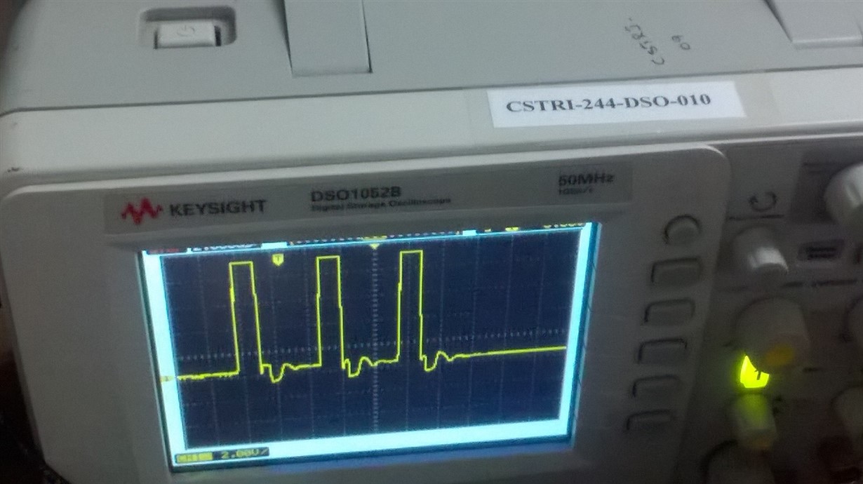
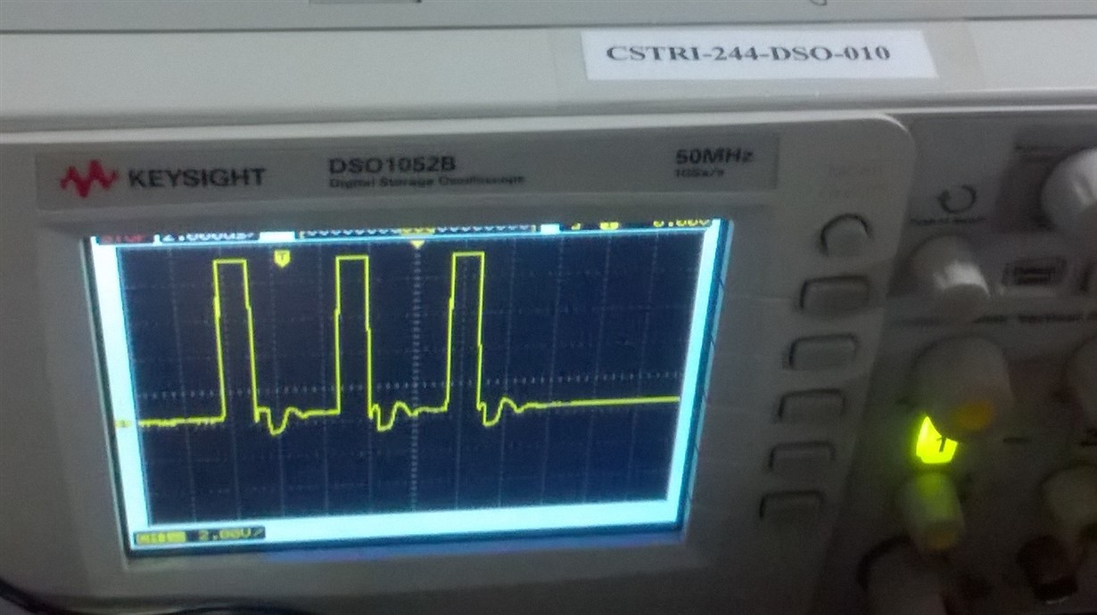
    Gradually Increased AC Voltage, At some voltage level like 90 Vac,  observed set of three pulses and after further increase, no pulses observed.
    while debugging, following devices on auxiliary side failed.
    Q3 - Internal Short
    D5 - Barrier diode short
    R7 - Resistance connected to DRV pin open
    they feel UCC28730 controller IC must have also failed. Request you to support on checking the IC condition.

    Request you to suggest possible causes for the failure.

    Rgds,

    Aravind.