This thread has been locked.

If you have a related question, please click the "Ask a related question" button in the top right corner. The newly created question will be automatically linked to this question.

LMR14030-Q1: synchronizing to a system clock

Part Number: LMR14030-Q1
Other Parts Discussed in Thread: TPS65320C-Q1, LMR14030

Hi team,

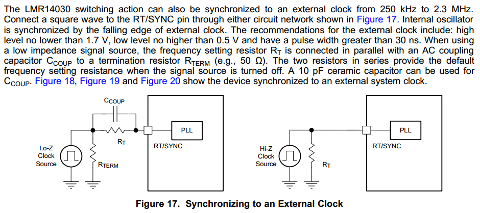
Could you help explain the difference between below synchronizing circuit?

Actually, there are some buck devices in TI, such as tps57114/12-Q1, tps65320C-Q1. They only choose one of the synchronizing circuits.

Can I use the Lo-Z clock source configuration for both situations? How to determine the termination resistor?

Thanks.

Dongbao

  • Hi Dongbao,

    Normally GPIO has limited current sourcing capability, it can't drive small terminal resistor like 50 ohm. so the R-term has to be 1K~5K ohm in most case, then calculate RT(freq) according to target switching frequency, RT=RT(freq)--Rterm.

    RT/SYNC pin has about 100pF parasitic capacitor, so Ccoup should be 470pF in actual application plus 3.3K resisitor in series with 470pF to limit current peak at clock edge.

    Hi-Z solution require the clock is high impedance at clock off or standby state, other wise the equivalent RT resistor maybe too small and cuase very high switching freq.

    B R
    Andy
  • Hi Andy,

    Thanks for your reply.

    • Can we use Lo-Z configuration for both Lo-Z and Hi-Z clock source?
    • For blow application, is it Hi-Z clock source or Lo-Z clock source? I think it should be Lo-z source since the Schmitt-Trigger Inverters doesn't have a high-impedance state, could you help check.

    Best regards,

    Dongbao

  • Hi Dongbao,

    Low Z clock can drive terminal resistor low as 50ohm, the Schmitt-Trigger normally cannot do this becasue of limited sourcing capability.

    In your application, if the clock is active before LMR140X0 is enabled, and clock closed after LMR140X0 disable, then you can use Hiz-Z clock source solution for sync clock.

    another simple couple solution is to add small Schottky diode between clock and RT/SYNC, of course you still need to place RT on RT/SYNC pin, the diode can isolate RT pin from the clock line no matter what's status or impedance it is.

    Feel free to send email to me if any further qustion.

    B R

    Andy Chen

    andy.chen@ti.com

  • Thanks for your support, i appreciate it.
  • Hi Andy,

    I am thinking another possible solution:

    Configuring the synchronizing circuit as the network for low-z clock source, setting the MCU I/O pin (clock signal output) to high if there is no external clock needed from BUCK, then the Schmitt-trigger will output low, the buck will operate at a frequency determined by frequency setting resistor.

    If you'd like to synchronize to an external clock, just let MCU I/O pin output clock signal.

    Since there is a 100ohm resistor parallel with Rterm in the circuit when Schmitt-trigger outputs low,  RT is equal to Rfreq.

    Would that be okay?

    Dongbao

  • Dongbao,

    You mean the clock chain is MCU I/O--------> Schmitt Trigger------------>RT/SYNC coupling netwrok------------>RT/SYNC pin?

    I don't know your wole system power tree, normally LMR140X0 is first satge buck converison for whole system, clock will be present later after LMR14030 anabled. so the MCU I/O maynot be high level before LMR14030 output is good.

    the key factor is that if no clock applied to RT/SYNC pin, the RT pin should only see RT resistor without any bias voltage.

    Network for low-z clock source is a nore fexible configuration, R-term has to be 1K~5K ohm in most case, then calculate RT(freq) according to target switching frequency, RT=RT(freq)--Rterm.

    RT/SYNC pin has about 100pF parasitic capacitor, so Ccoup should be 470pF in actual application plus 3.3K resisitor in series with 470pF to limit current peak at clock edge.

    feel free to call me if needed.

    B R
    Andy
    021-60316362