


I have a customer who used TPS54325 to convert voltage. The schematic is seen in Fig.1.
And the condition is Vin=5V, Vout=1.5V, and the voltage only power a CPU. And the output capacitors of the Buck is more than 60uF.
The customer find there will be voltage drop sometimes, the voltage will be 1.352V or other voltage sometimes and make their CPU reset. The customer told me when Vo and VFB is short for a sencond, the vo will rise very slowly, it will take about 7 hours to make the output voltage be normal. So I do the same test.
Here is the problem, when the power is on, I used a wire to link the Vo and VFB for just a second, then disconnect them. The Vo will rise very slowly, it will take about 4 hours to make the output voltage from 1.29V to 1.415V. The waveform of SW (channel 1) and Vo(channel 2) is seen in Fig.2. We can see that, the Vo is not 1.5V, and the switch frequency of SW is not 700kHz, but 2.26MHz. When I reset the power, and the Vo is normal, seen in Fig.3.
So I change a TPS54325, and short the Vo and VFB directly. But the output is not 0.765V, seen in Fig.3. I am confused about the reason.
Does the components selected in Fig.1 is right?
And how Fig.2 and Fig.4 happened?
Why the frequency and Vref is not stable?
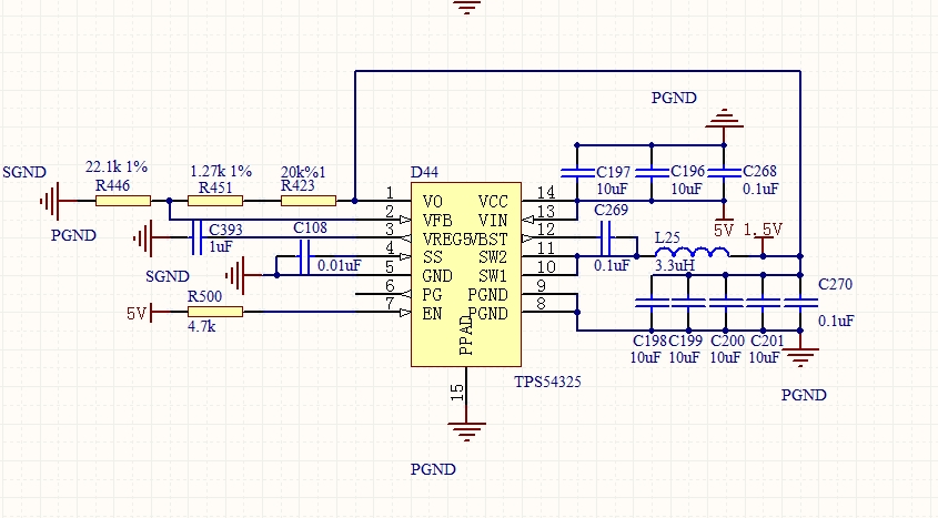
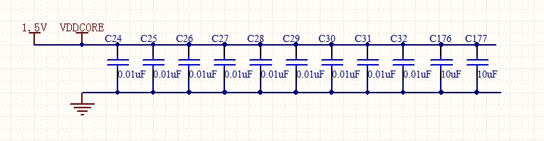
Fig.1 Schematic and load
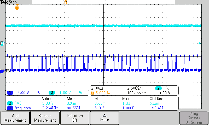
Fig.2 waveform of SW (channel 1) and Vo(channel 2), Vo and VFB short for a second, VFB is not 0.765
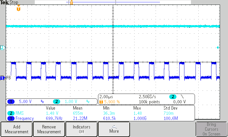
Fig.3 waveform of SW (channel 1) and Vo(channel 2), reset the power, VFB is 0.765
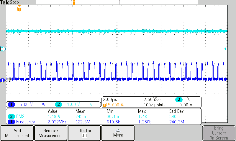
Fig.4 waveform of SW (channel 1) and Vo(channel 2) change a TPS54325, Vo and VFB is short, VFB is not 0.765
