This thread has been locked.

If you have a related question, please click the "Ask a related question" button in the top right corner. The newly created question will be automatically linked to this question.

UCC28951-Q1: 3.5KW Design with UCC28951-Q1

Part Number: UCC28951-Q1
Other Parts Discussed in Thread: UCC28950EVM-442

Hi,

We’d like to design a DC / DC converter using the UCC28951-Q1.

The specifications of output voltage is 380V and the specification of output power is  3.5KW.

We’d like to expand the output power by applying two transformers.

Which is the best way for us among the below following methods?


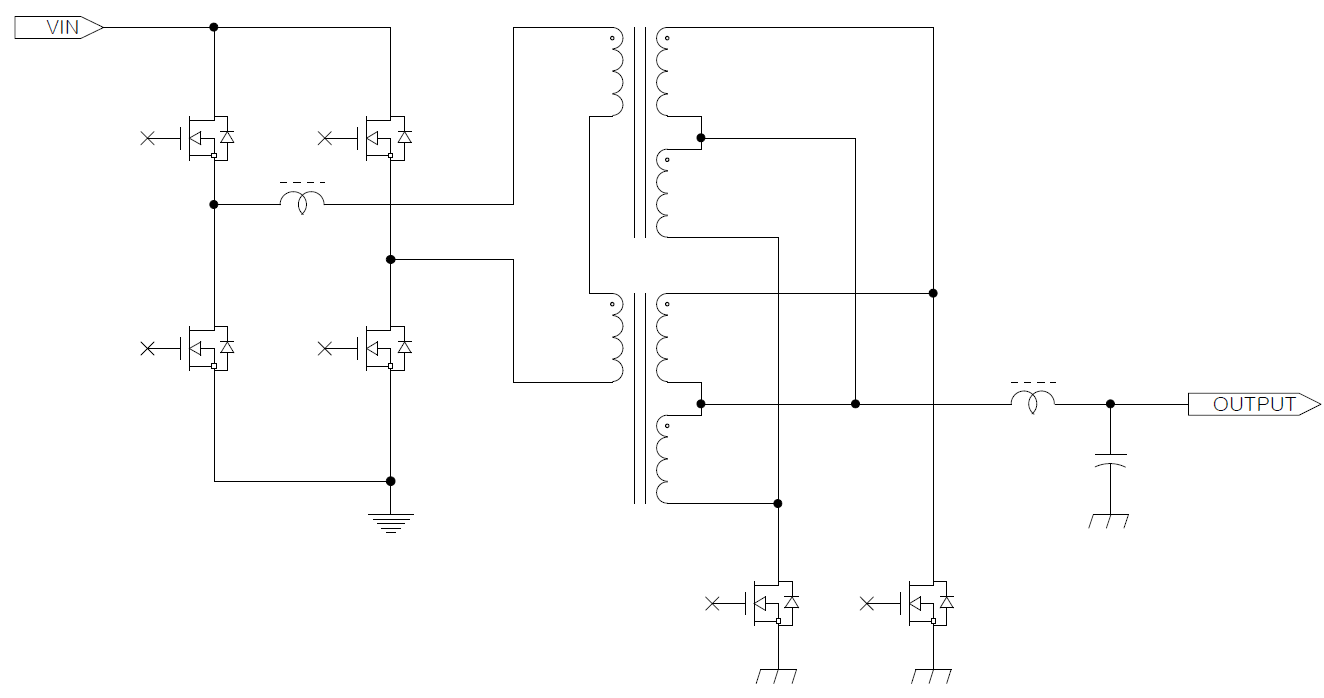
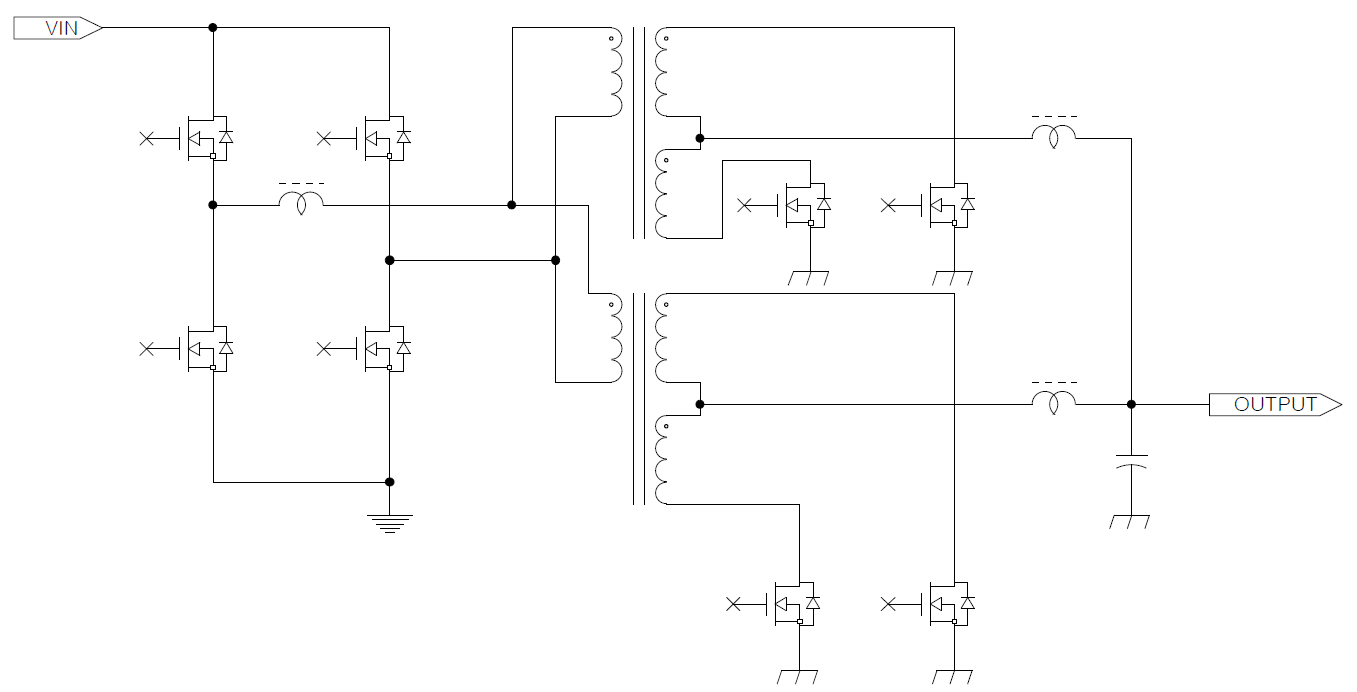
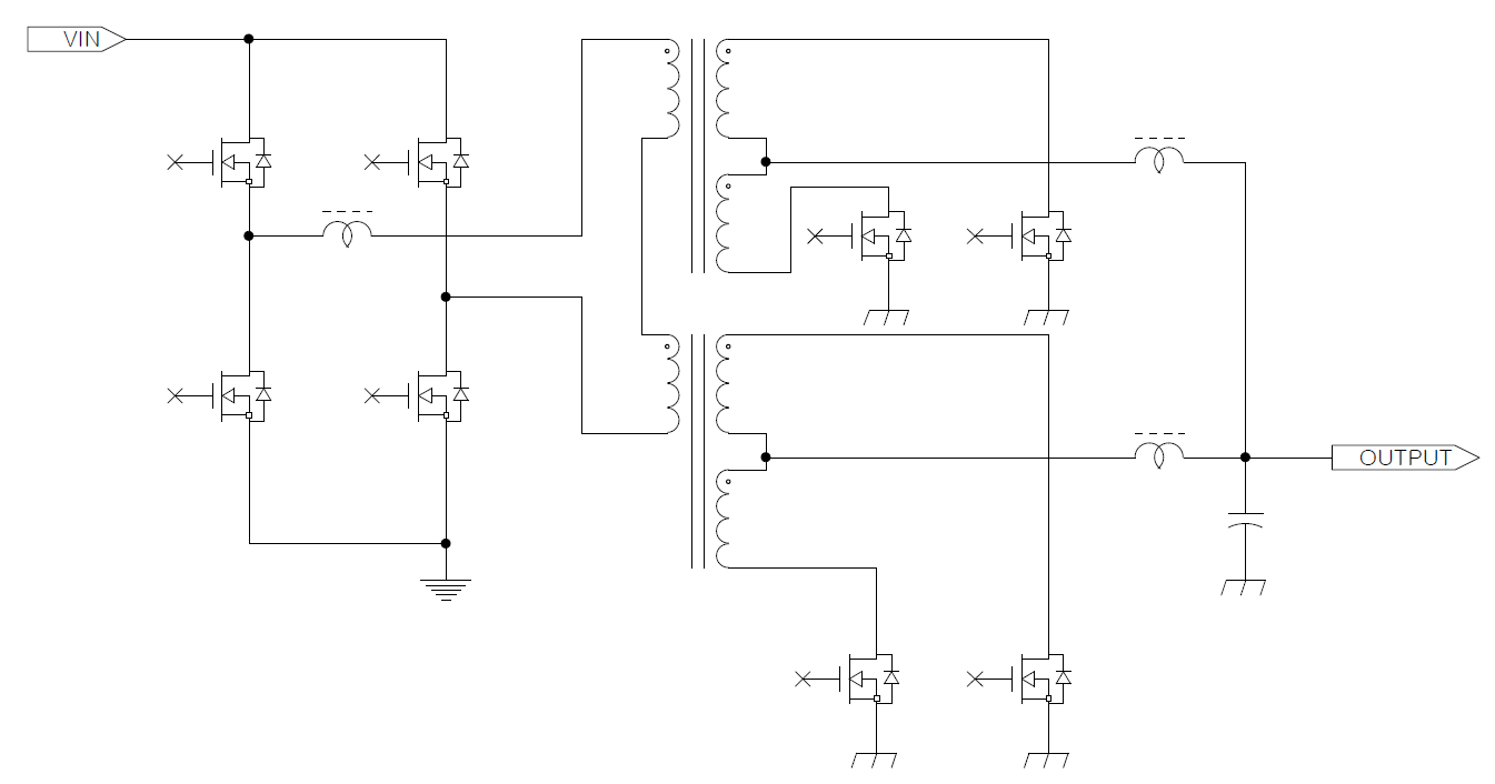
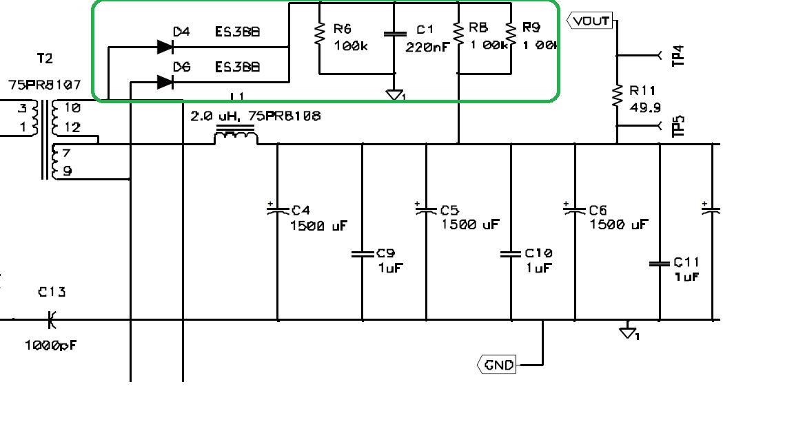
We cannot understand the below circuits in UCC28950EVM-442.

Please explain the operation theory for the circuit in the green box.

Do we have to apply this circuit  to our application?

Thanks


  • The components in the green box are a snubber circuit used to absorb inductive energy that would otherwise cause significant voltage spikes. They may or may not be needed in your own application - it depends on the detail design of the transformer secondary and the PCB layout.

    The higher power schematics have problems -

    First Schematic: The controller can control only the total current in the primary but it cannot control how it splits between the two paralleled transformer primaries. This will give problems in the paralleled secondaries too because the slightly different currents will give slightly different voltage drops and this will cause circulating currents.

    Second Schematic. Putting the primaries in series halves the voltage across each - assuming of course that the voltage splits equally. This means that for a given input power each primary will have to be sized to carry the full input current. Differences in magnetizing inductance will also mean that the input voltage splits unequally so that the secondary voltages will also be unequal. This will give very large circulating currents int the secondary.

    Third Schematic: The primaries are in parallel so it will have the same current sharing issues as the first schematic.

    Fourth Schematic: The primaries are in series so it will have the same issue as the second schematic. The secondaries will develop different voltages too but the inductors will keep the circulating currents lower.

    The fundamental problem is that, with a single controller, there are not enough control variables to force equal power sharing between the two transformers. the best way to increase the power is by building multiple, independent power trains controlled by independent controllers. The UCC28951-Q1 is a good choice because you can synchronise multiple devices and force equal power sharing across multiple, independent, power stages - each with its own UCC28951-Q1 controller.

    Regards
    Colin