This thread has been locked.

If you have a related question, please click the "Ask a related question" button in the top right corner. The newly created question will be automatically linked to this question.

UCC28730: UCC28730DR is restarted

Part Number: UCC28730

Dear TI,

Currently, zerowatt smps is assembled and tested.

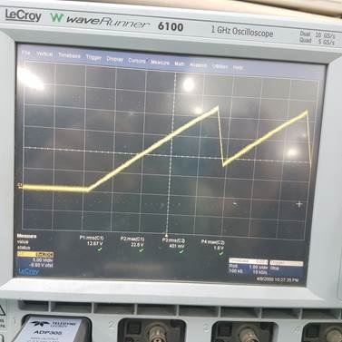
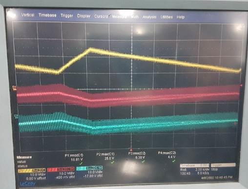
There is a phenomenon that the voltage rises at IC VDD and then starts to fall back to 7V again.

We also proceeded to TEST with DEMO BOARD TRANS, but there is no movement at all.

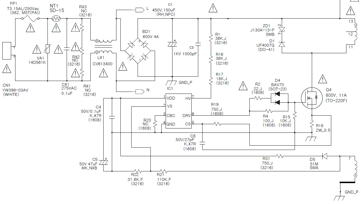
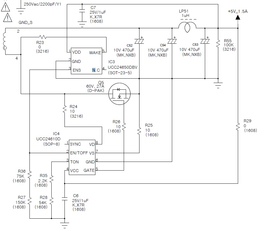
Please look at the schematic and make sure that you can advise.

Thank you.

  • BJ,

    Can you give some more information please?

    What exactly is going wrong, is the power supply shutting down and restarting? Under what input voltage and output load conditions?

    Can you include waveforms from the scope?


    From an initial review of your schematic, I think that the value for R31 (750 ohm?) is far too big. This resistor is intended to limit the peak charging of the VDD rail at heavy load due to the transformer leakage inductance. A larger resistor will limit VDD to a lower level at heavy load. But if the resistor is too large, it will cause VDD to drop much lower at light load, as Fsw decreases. If it's excessive, the VDD rail may not be able to stay above the UV level at no-load.

    In most cases, the value of R31 will need to be varied, depending on leakage inductance.

    The value of 750 ohm is very large, the UCC28730 EVM uses 24 ohm. This resistor value is typically in the range 1 ohm to maybe 47 ohm, depending on the power level and transformer leakage inductance.

    I would recommend maybe starting with a value of 10 ohm or 22 ohm.


    Thanks,
    Bernard
  • Hi Bernard,

    Thank you for your attention and support.

    We will share the waveform as shown below.

    -. Picture-1 => VDD

    -. Picture-2 => Yellow: VCC / Red color: VS / Blue: CBC

    => CS & DRV has no output.

    Thank you.

  • BJ

    Can you zoom in at the point where VCC reaches the start-up threshold (~21 V) and see if there are any short pulses on DRV? There may be only 3 short pulses, or maybe only 1 short pulse, or maybe none at all - but this will help to identify the potential problem.

    In the scope plot above, the timescale is too long, and the sample rate is too low, so the short pulses on DRV could be missed.


    I would recommend using this debug guide to help figure out the issue, it's applicable to all of TI's PSR Flyback controllers:

    www.ti.com/.../slua783


    What is your transformer turns ratio?

    What is the input voltage level for this test?


    Thanks,
    Bernard
  • Hi Brrnard,


    We have confirmed the problem today.

    It's problem is reinforcing the ground and the operation is completed.

    I want to give you a full schematic, PCB artwork, and a transformer specification.

    Can you give me your email? Because the above schematic are not all.

    It is not a single output but a multi-output schematic.

    There is no problem with single output, but there is an IC problem when turning on / off multi output.

    I am sorry to interrupt you but We need your help to win and get this opp.

    Thank you

  • BJ,

    You can email all details to me at John.stevens@ti.com and I will support in my team going forward.

    Regards
    John
  • Hi John,

    I sent the materials by email.
    Please check and reply.

  • Will do. Thanks BJ.

    -JS

  • Hi John,
    We are waiting for your answer.
    Please check and reply.
  • BJ,
    I will close the thread and respond in email.
    -JS