This thread has been locked.

If you have a related question, please click the "Ask a related question" button in the top right corner. The newly created question will be automatically linked to this question.

TPS62130: TPS62130-Not generating proper output voltage.Urgent! Please help!

Part Number: TPS62130

I have 6 pieces TPS62130 on my board. Sometimes one of them does not work when I enter 12V input pwer. But sometimes it works. This is a random event which affects stability. I need to improve it. Since it does not work when I enter 12V input pwer, I need to shut down 12V and wait for more than 25 seconds, and then enter 12V again, it may rework to generating proper output voltage.

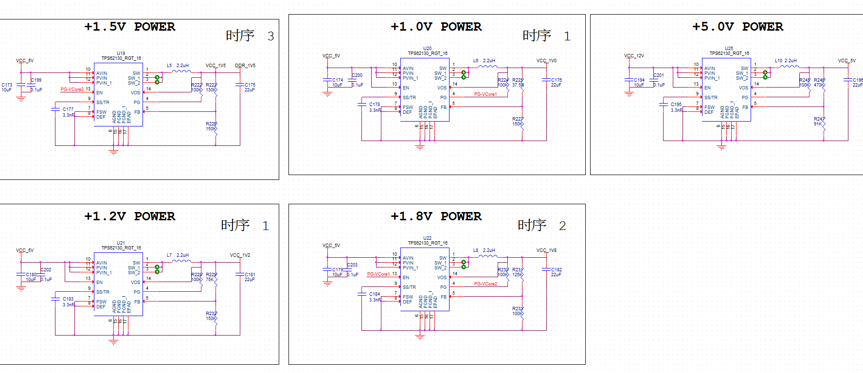
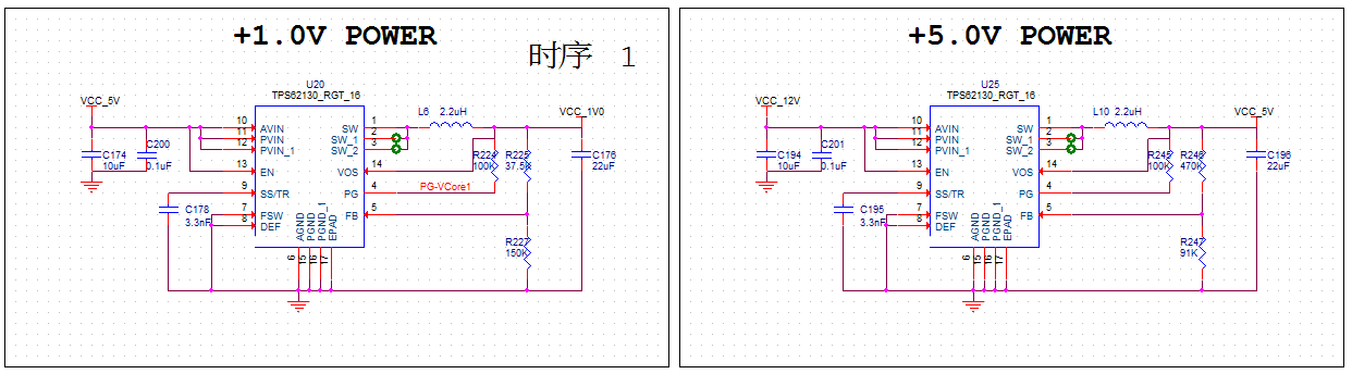
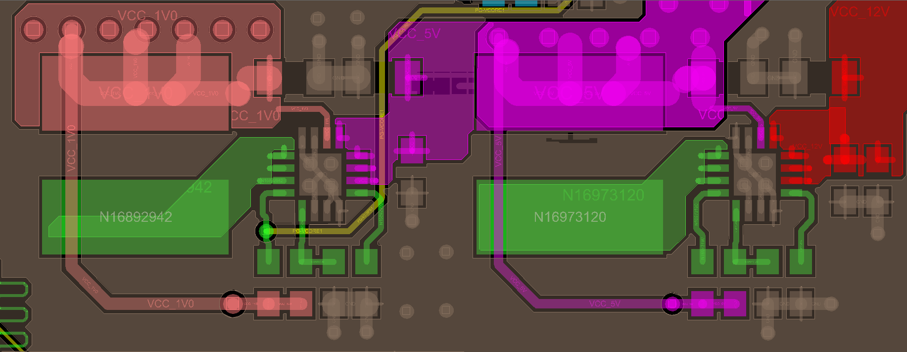
Here are the schematic and layout.

Here are the signals in the 12V-TO-5V unit when it works well.

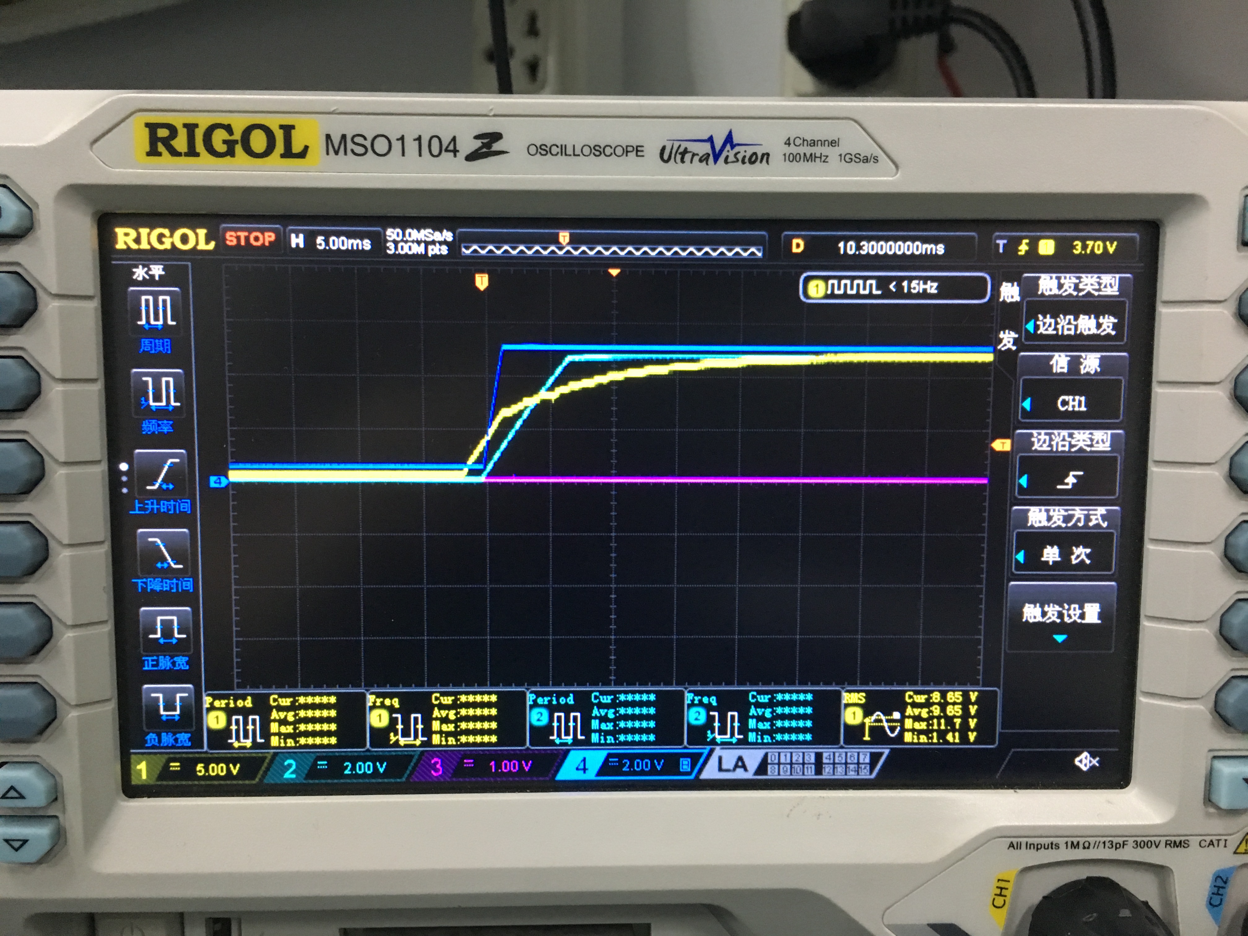
Yellow is Vin and EN, 12V, light blue is SS / TR, dark blue is 5V Vout.

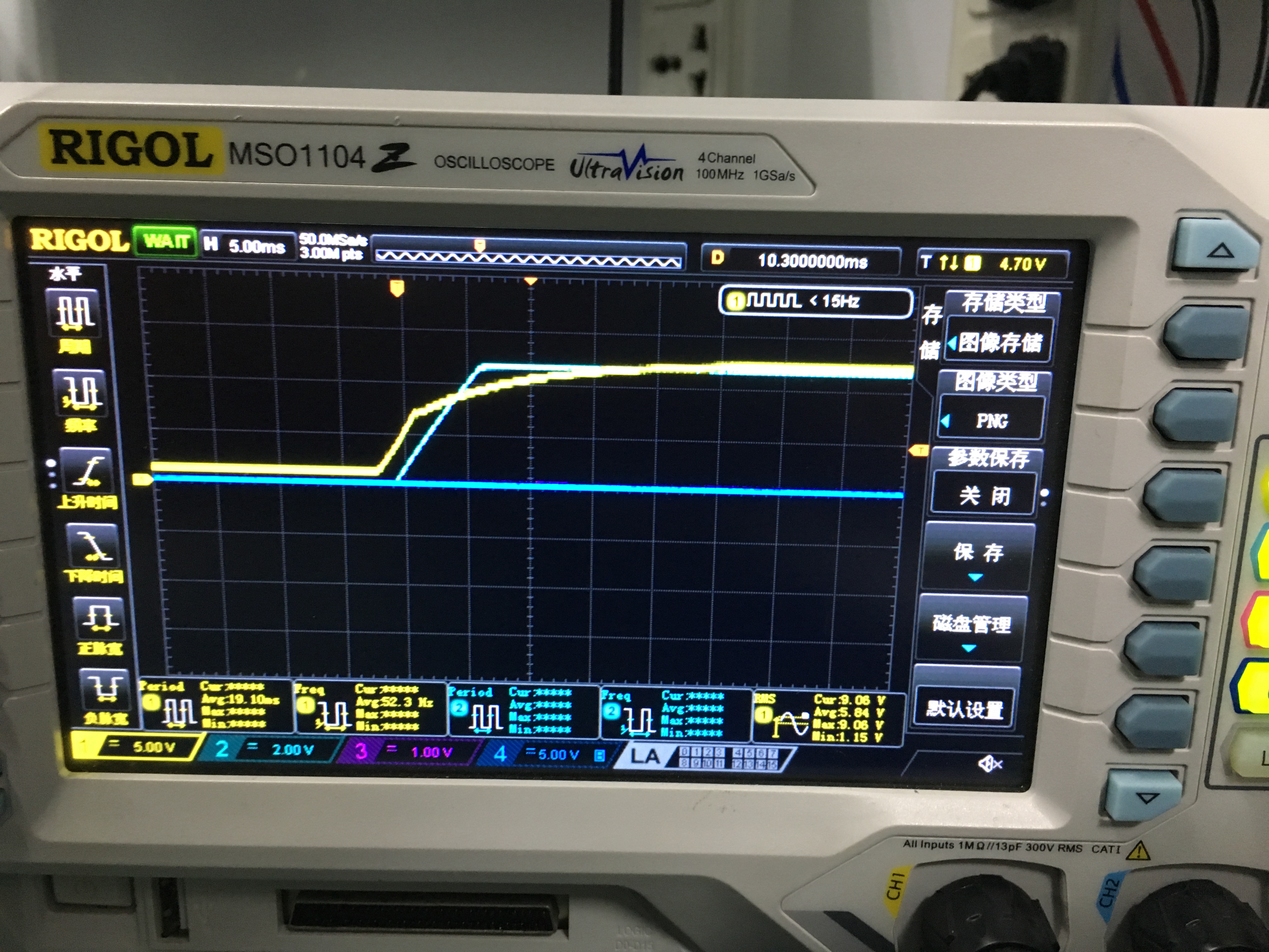
Here are the signals in the 12V-TO-5V unit when it does not work.

Any help would be much appreciated as this is the only thing holding up production and it is urgent!

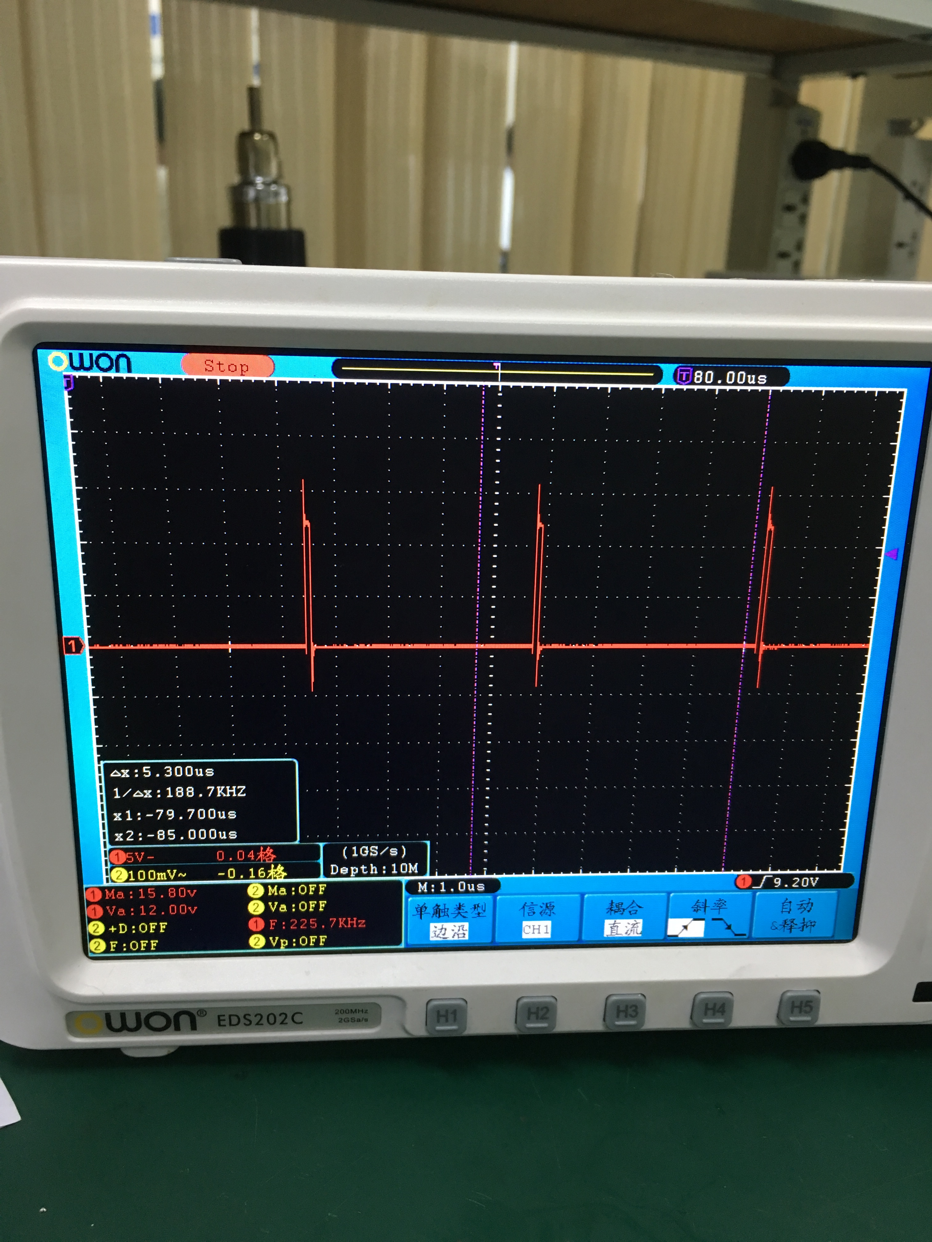
Besides, when I use the DC electronic load machine to test one unit of tps62130 on my board, it works well up to 3A current in the CR mode even if I turn on and off 12Vin repeatedly. However, in the CC mode above 1.6A current, it only generating about 200mv. The SW signal is below. what is the state of work?

  • Hello,

    are you using an electronic load or a real load?
    Electronic load can cause an issue at start-up since it behaves differently to a real load.
    Please retest with either resistors or a real system load.

    Best regards,
    Ivo

    Texas Instruements
  • Thanks, I will retest with a resistor.
    But what is the reason for the malfunction upper: sometimes it does not work(output 0V) when I enter 12V input pwer, I need to shut down 12V and wait for more than 25 seconds, and then enter 12V again, it may rework to generating proper output voltage. This happens in my real system load.
  • Hello,
    Could you change your design/schematic and connect the PG pin of the 5V Vout converter with the EN pin of the VCC_1V converter? This provides a power sequencing and reduces the inrush current and potentially related start up issues.

    I checked your layout and I think that the input and output capacitors are not routed to the PGND pins on a top layer - the connection seems to be done with vias to the GND layer. Please compare with our recommended layout in the data sheet.

    Best regards,
    Ivo
  • Thanks, actually other TPS62130 units have power sequencing, but 1.8V output also appeared fault.

    I agree with your opinion about the layout and I can change the design. And is there any other possibility of causing this malfunction? As this phenomenon appear at random and it is difficult to reproduce,  I must consider all the affected factors and make this urgent project done.