This thread has been locked.

If you have a related question, please click the "Ask a related question" button in the top right corner. The newly created question will be automatically linked to this question.

TPS54228: sw pin control in tps54228

Part Number: TPS54228
Other Parts Discussed in Thread: TPS561201, INA199, LM321, LMV431

Hello,

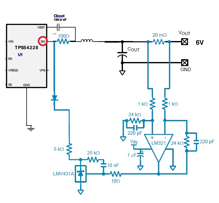
I would like to add another circuit as the attached rough schematic in order to limit the current of tps54228 to 1A. I assumed that it will influence sw pin by that but it doesn't affect the current operation of the ic after a few tests.

Please advice is this implementation on sw pin is correct? or if not, how can I use this feedback circuit with other pin# or add other configuration feedback to limit the current?

Thank you,

  • Hi Bar,
    1. suggest to use TPS561201 for 1A output current and limit.
    2. the schematic which you posted is wrong. 100 ohm can't be in series to inductor and SW node.
  • 1.Why do you use LM321? Pls use INA199..
    2.Pls use FB pin to realize your current limit.
    2.Pls optimize your circuit with LMV431 when using FB pin.
  • Hi Bar,

    For my curiosity, why would you like to use a 2A device and limit the DC output current to 1A. From my understanding of your circuit, you are planning to branch and dissipate the current over 1A thru external SW circuit? Is it correct? I think it is not very efficient considering the power loss on shunt R and the logic circuit leakage. It will be more efficient to use either FB pin or EN pin to control the current limit. Let FB higher than Vfbref or lower than 65% Vfbref will make the device power off. Pull EN to low will also get the same effect.

    What I recommend is to use a 1A current limit device or a load switch IC to limit the output current to 1A. It will be a more decent and easy to use design.