This thread has been locked.

If you have a related question, please click the "Ask a related question" button in the top right corner. The newly created question will be automatically linked to this question.

BQ24104: Can not charge battery 18650 with BQ24104

Part Number: BQ24104
Other Parts Discussed in Thread: BQ29209

Hi everyone
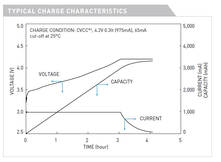
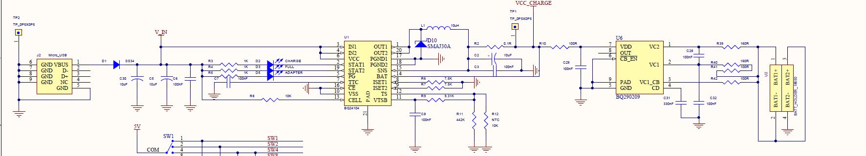
I have just make a charge board for 2 cells18650 battery ( Vavg =3.7V, Vfull= 4.2V, Iload =2A) with BQ24104
I do schematic similar as example circuit in datasheet, using USB port for charge.

Info of battery : hshop.vn/.../pin-sac-18650panasonic-3-7v-3700mah

when i install a 2 cell battery, i dont see led for charge blink and led for adapter bright, normal when do not install cell, led blink and birght.
I checked in datasheet, maybe MUST Vin > Vcharge so can not use USB port charge for this circuit
Can I make parallel cells to get Vcharge about 3.7 to 4.2 ?
maybe BQ24104 can drive enough charge current?
Please help me to solve this problem
Thanks

  • Hi everyone
    Can you help me to solve this problem?
    Thanks
  • Hi,

    You need to set CELLS pin to GND or leave float to charge up to 4.2V on the battery. You can see the explanation on page 5 on the datasheet, the description for the CELLS pin.

    Regards,
    Steven
  • Hi Steven
    I known this point, but i now i want to charge 2 cell series with about 8.4V
    I tried to input power with 12VDC ( cells pin pull high via 10K to VCC), but led on stat1 always blink, and output voltage for charge not have appearance ( i checked about 6.4V, nearly equal a volage of 2 cell series), so i think problem maybe in my config circuit for TS, or RSET1 and RSET2.
    Can you help me to solve this?
    Thanks
  • What is the voltage on TS, VTSB, VCC, and BAT? An oscilloscope waveform of IN, OUT and BAT may help as well.

    Also, try adding a schottky from PGND to OUT. This may help.

    Regards,
    Steven
  • Hi Steven
    Thanks for your support.
    I checked voltages on bellow pins with VOM, i dont have ossciloscope now

    * VCC : 12V
    * VTSB : 3.1V
    * TS: 1.6V
    * BAT: 5.4V

    About adding schottky diode, maybe this dont need for BQ24104 ( follow datasheet) ?
    Also, Ill try to add

    Thanks
  • Hi,

    Use ceramic caps for input and output, placing 2x10uF ceramic on input and 2x10uF ceramic on output, replacing C5 and C2. Also, use 0.05ohm for R2 and 4.7uH for inductor L1, which is recommended for 2A output. You can also follow the example layout on figure 24 of the datasheet. Change both RISET1 and RISET2 to 10kohm for 2A charging and 200mA for precharge/termination.

    Regards,
    Steven
  • Hi Steven
    Thanks for your help.
    Really i have just checked on schematic and have wrong, the THERMAL pin isnt connected, so i think this is my issue.
    I'll fix and order new PCB for testing

    About current charge limit for NCR18650B Li-Ion batterry, i see it have a max charge current about 1.5A, so can I charge with 2A as you told?
    I have an unclearly point about calculated a time for full charge battery?
    Can you help me show a formular to estimate a time for charge?

    Also, in this power charge system, the load system must get out before/after Rsense (R2 in above schematic)
    Do you have any idea about this?

    Thank you!
  • Hi Steven
    I also need to add li-ion batt protector IC.
    Can you give me advices?
    Thanks
  • Hi Steven
    Here is the specs of NCR18650B batt:

    Thanks

  • Hi Steven
    Can you help me?
    Really I need to solve this issue asap
    Please help me
    Thank you.

  • Hi,

    Is the system going to be on all the time? What is the average current that will go into the system? What is the peak current into the system?
    Also, the max charging current for this battery appears to be 1A. Do you have a link to the full spec of the battery?
    As for a battery protector IC, please start another thread to ask for that.

    There are two ways to tackle the system connection (assuming a charging current setting of 1A):
    1. Connect the system before the sense resistor: This will not affect charging current regulation, meaning that the system is not limited to the 1A charging current limit. But you need to make sure that the total current going through the bq24104 is not more than 2A, which is the maximum we recommend.

    2. Connect the system after the sense resistor: the system current will be included in the charging current regulation, meaning that total current to system + battery will be 1A.

    Regards,
    Steven

  • Hi Steven
    I changed the schematic as you told and same in datasheet ( before sense resitor, with load current for system about lower 1A)
    I also add BQ29209 to protect battery, but im not sure about OUT pin? Is this correct?
    I think we can disscuss in here and maybe don need waste more space of forum:)
    Thanks for your help:)

  • Hi,

    The battery protector ICs is done by a different group than mine. If you would like extra help on the battery protection, create another thread with that device number.

    As for the system load current, it is good how you placed it. Make sure that system current + battery current do not exceed 2A.

    Regards,
    Steven