This thread has been locked.

If you have a related question, please click the "Ask a related question" button in the top right corner. The newly created question will be automatically linked to this question.

UCC27201: UCC27201 fails

Part Number: UCC27201

This part is failing at random times throughout the motor drive cycle. The failure is exhibited by bubbling and cracking in the part. Clearly a sign of overheating, probably caused by an over-voltage condition or negative voltage on one of the pins.  Typically the failure is associated with a particular phase, 4 out of 6 on the same phase.  I am attaching both my schematic and layout. Any help solving this would be grand.

7455.Doc1.docxMotor Drive Rev 4.zip

  • Hello Mike,

    Thank you for the interest in the UCC27201 half bridge driver. I am an applications engineer with the TI High Power Driver group and will work to resolve your concerns.

    To understand what may be the cause of the issue with the UCC27201 random failures, I will need to get more details about your application.

    I see on the word document with the schematic the VDD to the UCC27201 is 12V, but Vbatt range is not specified. Can you confirm the VDD of 12V and provide the Vbatt voltage range to the half bridge input?

    Can you provide the operating frequency of each half bridge phase, to help determine driver power dissipation?

    Power converters switching high current and/or voltage will almost always have some voltage overshoot and/or undershoot due to the di/dt and dV/dt present on the power train switch nodes. There is possibility of induced noise on control signals, including driver inputs from the close proximity to the power converter.

    Can you provide scope plots of the following: 1) HO-HS (with differential probe if possible), LO to ground, and HS to ground. Record several cycles on one recording, An zoom in on the time base to see the details of rising and falling edge overshoot and undershoot details. 2) scope plot of LI, HI, and LO referenced to ground, and HO-HS (with differential probe if possible).

    Without having more details of the operation, it is difficult to determine what may be the cause of the driver failures.

    Regards,

    Richard Herring

  • Hi Mike,

    I work with Richard who posted above, is there any update with this issue? Could you let us know if the problem still exists or what you did to fix the issue? I will for now assume this has been resolved.

    Thanks,
  • The issue has not yet been resolved.  We suspect a spike we are seeing on the HS line when commutating from one phase to the next is the culprit. That would kill the driver. We are increasing the Rg on the high side from 4.99 to 10 ohms to slow down the turn on/off of that MOSFET.  If this doesn't work we will put a snubber on each phase line.

  • Thanks for the update Mike!

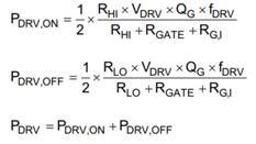
    Make sure power dissipation for each HO/LO driver is taken into account to minimize driver power dissipation. Since Rgate needs to be sufficiently large to limit output current capability the majority of the gate drive power loss is dissipated in Rgate. It is safe to assume that with low value gate resistors (< 5Ω) most gate drive losses are dissipated in the driver with minimal effect on output current capability. The snubber will help with ringing and your issue if it is the root cause, an RC snubber can be placed on LS drain to source or an RL snubber can be placed in series with the resonant circuit.

    The equation below highlights this. Read more on page 13 here: www.ti.com/.../slua618.pdf


    Let me know if this fix does not help so that I can!

    Thanks

  • Hi Mike,

    Just checking in with this issue, any update?

    Thanks,