Part Number: BQ24620
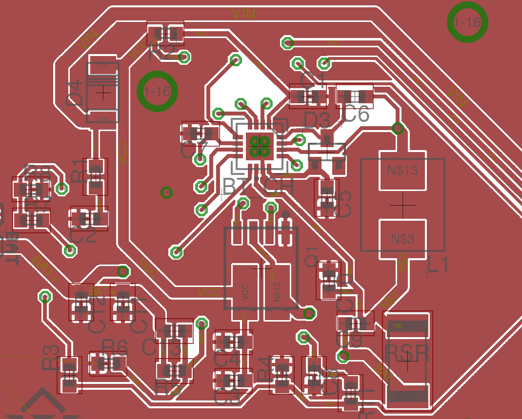
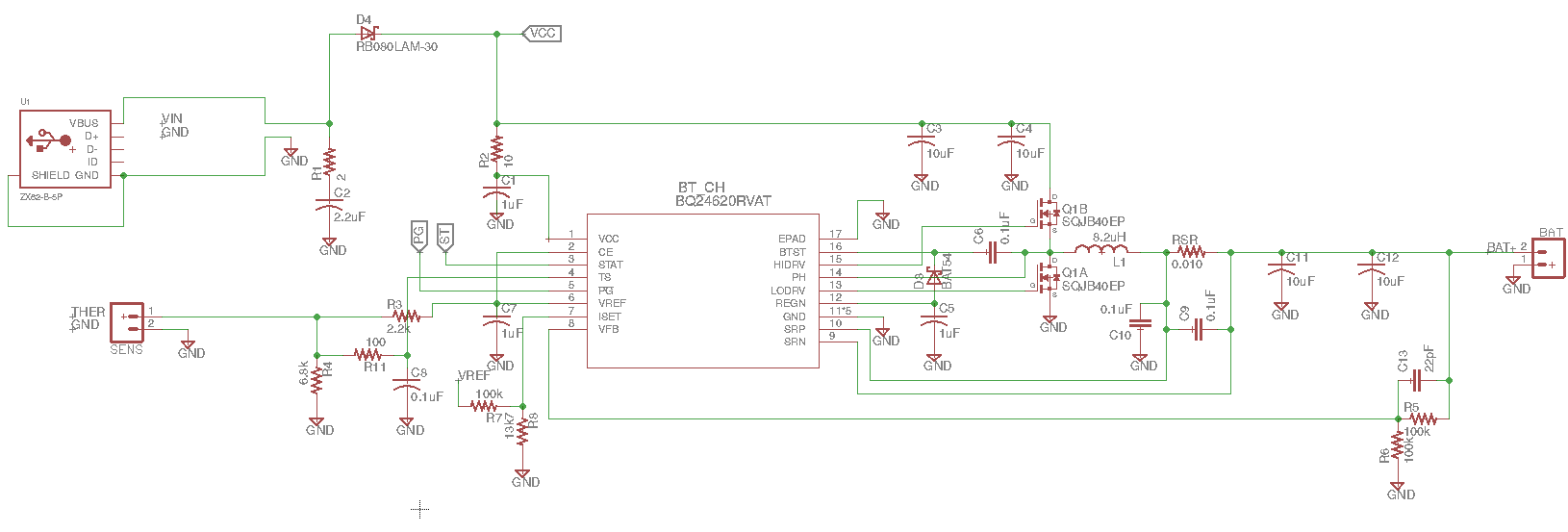
Hi, I've implemented the following circuit, based on the one from the datasheet, for charging at 2A a single cell lifepo4 battery. By now, on testing, I've changed the mosfet for the one used in the data (Sir246DP) and I've set the charging current to 4A (R8 is 32Kohm).
As far as I understand, the chip uses one of two operational modes: synchronous and nonsynchronous. Nonsynchronous is forced when the charging current is below 0.5A, when the battery voltage is below 2V or when the average charging current is lower than 0.125 A. The charging current is measured using the SRP-SRN voltage. During synchronous the charging current floats around the desired value, while during nonsynchronous it goes to zero and then the high-side mosfet is turned-on again.
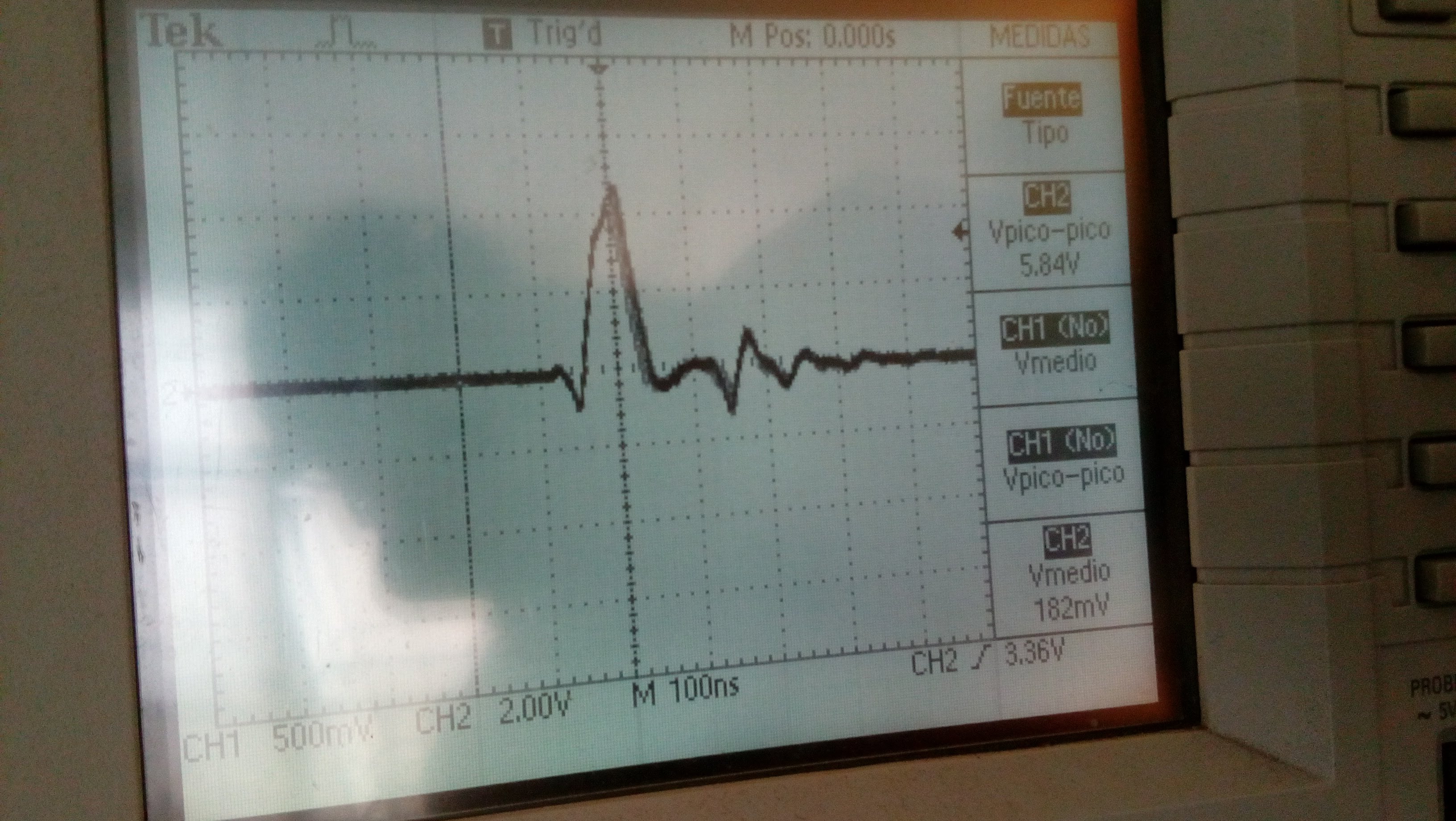
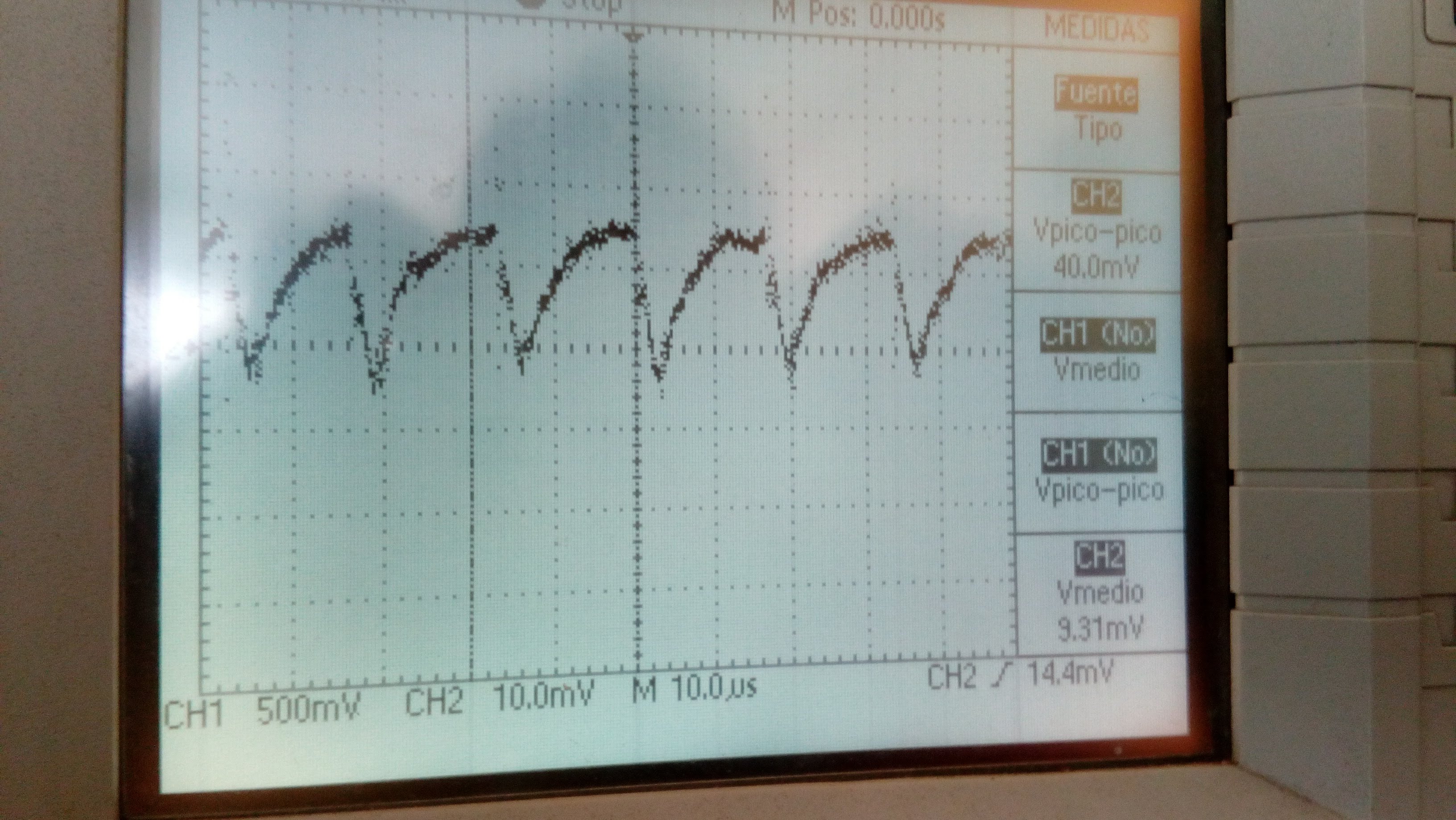
Here is a snapshot of the SRP-SRN voltage (50mV, 50 uS per division):
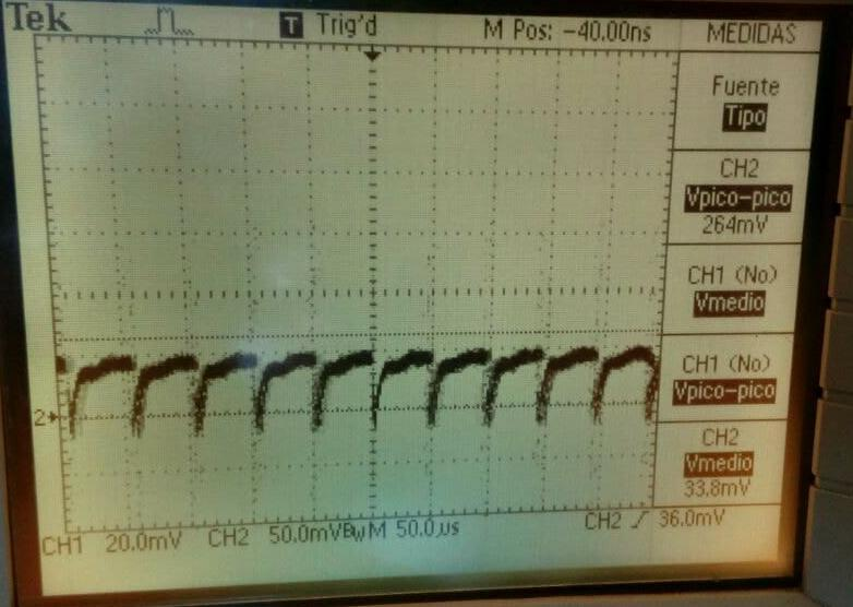
Then, it seems to me that given that the current goes to zero, it is working in the nonsynchronous mode, but no conditions are being met. Also, the low-side mosfet is never turned on (nonsync. mode, bootstrap capacitor never goes below 4.2V).
Could you help me to understand why the module decides to use that mode? Thanks in advance!