This thread has been locked.

If you have a related question, please click the "Ask a related question" button in the top right corner. The newly created question will be automatically linked to this question.

TINA/Spice/LM79M12: Toroidal Transformer 12V DC from 6VAC

Part Number: LM79M12

Tool/software: TINA-TI or Spice Models

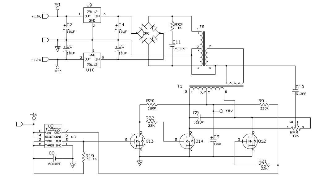
There is a design. In the design 6V AC signal is transformed to +-12V DC signal by using transformer and rectifier. I try to understand the design. Transformers are toroidal type . I dont know number of turns or other values of transformers. ( How can I determine that ? ) . I try to add on Tina but I cant find any appropriate transformer to simulate. Could you help me about how the circuit works ? I want to learn output voltage value of transformer before or after rectifier. I add the design. 

  • Hi Yildirim,

    The spice models provided by TI are meant to simulate our devices. It seems that your questions are with the theory of the design application and the transformers rather than the TI products. The source of the design will be a better resource to answer your questions.

    Very Respectfully,
    Ryan
  • Hi Yildirim,

    the working principle of this circuit is rather simple: U8 produces a clock frequency and turns Q12 and Q14 alternately on and off. This causes a periodically changing magnetic field in T1. As consequence, in the secondary winding of T1 an AC voltage is induced, which drives the primary winding of T2. Finally, in the secondary winding of T2 another AC voltage is induced, which is rectified and regulated to +/-12V.

    Two transformers are used in order to reduce the capacitive coupling between the 6V supply and the regulated output voltages +/-12V. With only one transformer the interwinding capacitances would cause lots of stray capacitance.

    R23 und C10 improves the symmetry and by this further reduces switching noise on the output side.

    The loose coupling between input and output windings of transformers is intended, as is the low clock frequency and the slow turn-on and tun-off of Q12 and Q14. All of this is planned to reduce the switching noise. As consequence the efficiency of this switcher is rather poor. But this doesn't matter, because the main purpose of this circuit is to keep the switching noise and the stray capacitance as low as possible.

    Kai