This thread has been locked.

If you have a related question, please click the "Ask a related question" button in the top right corner. The newly created question will be automatically linked to this question.

bq76940: circuit design and spec problems

Part Number: BQ76940

Hi Engineer,

My customer has some questions on the BQ76940 spec and circuit design.

1. What's the Max balancing current Bq76940 could support with external balancing circuit?

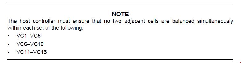
2. on datasheet p.30, is the cell balancing could be synchronous at the same group?

Or for example could VC1,3,5,7,9,11,13,15 could balancing at the same time?

3. at EVM user guide p.56, if I would like add a 12V external voltage source with parallel to the battery source and enter the REGSRC.

Could I design the circuit with adding an extra diode like the picture below? or do you have another suggestion if there is any risk?

the purpose of this design is to decrease the power dissipation from battery once there is an adaptor input.


4. Is the BQ76940 internal digital core(MCU) powered by REGSRC or battery?

there are a lot of questions, looking forward to your reply, thanks. 

  • Hi Pearl,
    My first reply disappeared, so this may be a duplicate.
    The application note www.ti.com/.../slua749 may be helpful.
    1. The external FET and resistor will determine the balance current. The voltage available to drive the FET gate will be limited to approximately half the cell voltage. The FET should have a defined RDSON at that voltage or below. FETs which can support large currents with low Vgs may be limited. The power in the FETs and resistors will typically be in the battery and may limit the balance current.

    2. Cell balancing within a cell group is synchronous. Balancing C1,3,5,7,9,11,13,15 will work. Cells 5 and 6 are in different groups and could be balanced at the same time, so the bq76940 could balance 9 cells at once: C1,3,5,6,8,10,11,13,15. Since groups are not synchronous, be aware of the common path resistance shown in figure 8 of the application note.

    3. Section 9 of the application note may be helpful. I don't see a risk from supplementing REGSRC with another supply, but if your battery provides a higher voltage from Q14 it may not provide the desired benefit. If you have a 12V which is always present you could operate REGSRC from that 12V and not used the Q14 circuit.Do note that the FET drive will come from the REGSRC voltage with a drop to the FET gate drive voltage.

    4. Both BAT (with VC5X, VC10X) and REGSRC supply current to the circuits. BAT pins provide the voltage measurement circuit while REGSRC provides for the FET drive, REGOUT, current and interface circuits. See the app note section 9. The bq76940 data sheet shows the supply currents to the REGSRC and BAT power pins in different modes. REGOUT and the FET drives come from internal linear regulators from the REGSRC pin, so currents for these loads will be directly added to REGSRC.
  • Hi WM5295,
    For the question 1, then what's the max limited current to design?