This thread has been locked.

If you have a related question, please click the "Ask a related question" button in the top right corner. The newly created question will be automatically linked to this question.

TPS7A83A: Maximam Capacitance

Part Number: TPS7A83A
Other Parts Discussed in Thread: TPS74901, , TINA-TI

Hi

My Customer has question.

Customers are considering replacing TI 's LDO. (TPS7A83A & TPS74901)

LDO.pdf
I confirmed the circuit specification of the latter stage and confirmed that very large Capacitance was implemented.
Also, reducing this output capacity is impossible because of load demand.
The above 2Devices has no upper limit of the output capacity, but can this be replaced by this circuit specification?

Best Regard

T Kishi

  • Hi T,

    both datasheets tell that the output capacitance can be increased without any limit.

    Kai
  • Hi T Kishi,

    As mentions, we do not have a maximum capacitance specification for these LDOs. With large output capacitance, you will have a longer startup time and will need to consider the potential of reverse current if disabling the input voltage. We have used TPS7A83A with up to 1 mF of output capacitance without any stability issues.

    What are your current requirements for your application? TPS7A83A is part of a family of LDOs that can be tailored to your specific application needs. Furthermore, the family also includes several dual LDOs that can help further isolate your output rails if desired.

    Very Respectfully,
    Ryan
  • Your 1mF capacitance is a helpful application case for me , I would like to use 2mF,  but is not connect to the ouput of the ldo,  it is pass a R0.1, so this capacitance is a RC low pass filter at the output of ldo , also  it is the bulk capacitance for the following circuit which has a dynamic current.  The fc of the low pass filter is about 700hz, it seems ok.  But I am not sure if it is better to use a LC filter?  LC filter's response is better ,but a large value of L may decrease the dynamic current requirement ?      

  • Hi Liang,

    in any case the output capacitor of TPS7A83A must be connected directly to the output pin of regulator! If you additionally want to filter, then you must do this behind the decoupling cap. Your filter arrangement could look like a pi-filter then, first the decoupling cap of regulator then the R or L and finally the filter cap of this filter.

    If you design a LC-filter keep in mind, that this can result in heavy ringing. To dampen the ringing there must be a series resistance R within the LC-filter of R>=SQRT(2L/C). This can be part of the L or C (ESR) or you could add it and put it in series to the L. Also the snubber method can be used: You put a cap with a series resistor in parallel to the filter cap. Run a TINA-TI simluation to find the details by yourself.

    Kai
  • Thanks alot !I will study the LC filter ,I am not clear about your LC equation. But it seems LC is not a better method here, I would like to get a maximum power load regulater and line regulater performance.
    Sure if use RC filter,I will make a pi-filter,my plan is the pre-pi-filter capacitance 100uf( this is the Cout),the R is 0.1ohm,and post-pi-filter C is 2000uf(may use several 300-500uf parallel). Using the little 0.1ohm is to get a small votage ir drop. and the ldo total divider resistance to the GND is 10e6ohm, so the discharging current is very little .
    And your last suggestion,use several resistance parallel with post pi-filter capacitance ? what is the reason?
  • Hi Liang,

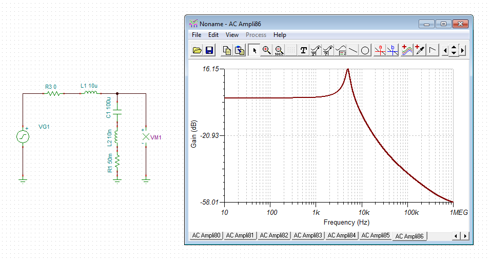
    here's an example for the snubber method. Assume you want to have a LC-filter with a 10µH choke and a 100µF electrolytic. Because you need a high damping you choose an electrolytic with an ESR of 50mR. Unfortunately this filter will show heavy ringing because the resonance isn't sufficiently damped:

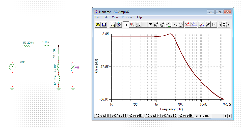
    The usual methode to increase the damping and to avoid the ringing would be the introduce of a resistance in series to the choke, according to R>=SQRT(2L/C)= 0.45R. Unfortunately, the load current will create a voltage drop across this damping resistance. A resistance of 0.2R would give the following frequency response:

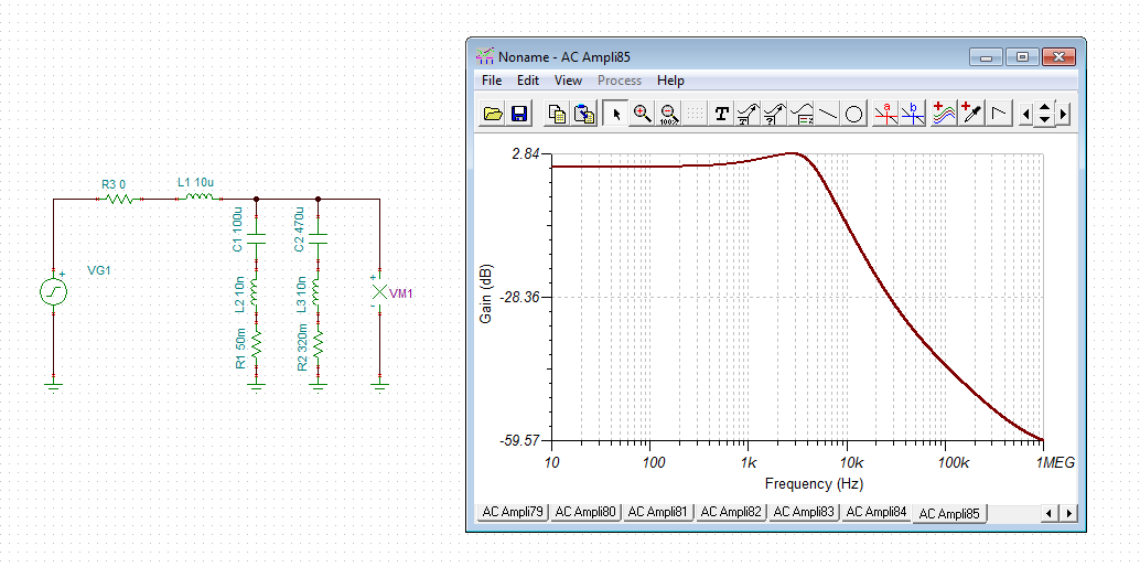
    The resonance and the ringing would be acceptable now. But what, if the voltage drop is still too high? Is there another method to generate enough damping without causing a too high voltage drop? There is! When connecting a series combination of 470µF electrolytic and 320mR resistance in parallel to the 100µF/50mR electrolytic, the resistance in series to the choke can be omitted without sacrificing the damping:

    The 470µF/320mR snubber is now providing the damping.

    Kai

  • that seems amazing,I am not inderstand the theory how the rc function can decrease the resonance,but it seems a good method to solve the two reqiurement. Another important problem is when the load current change fast ,the inductance can block the ldo‘load regulation . Although  LC can give a good performance without a IR drop voltage,the rc filter may be the best solution to get a better balance bettwen filter and load regulation?(select small R,while select large C)