This thread has been locked.

If you have a related question, please click the "Ask a related question" button in the top right corner. The newly created question will be automatically linked to this question.

BQ76930: Cell 6 measure no voltage

Part Number: BQ76930
Other Parts Discussed in Thread: BQ76940,

Hi,

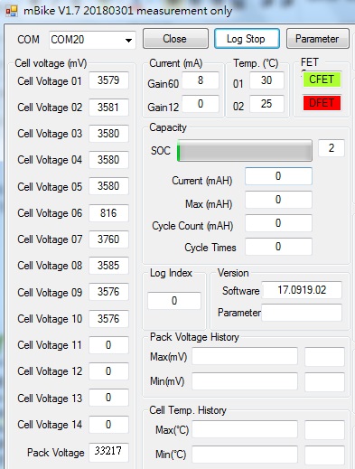
While testing in production line, there some samples failed because of cell 6 no voltage after short circuit testing(P+ short to GND)

Form tool below can see Cell 6= 0.816V , Cell7=3.76V...etc., and the real measurement at battery side is 3.58V

What customer had measured are:

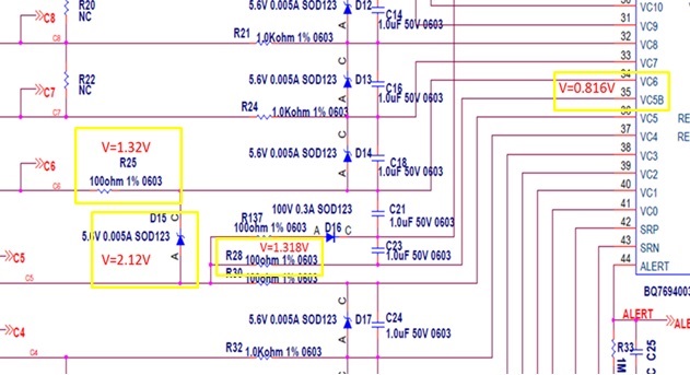
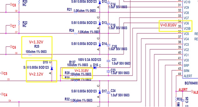
R25= 1.32V, R28=1.318V ,D15=2.12V and VC5B-VC6 = 0.816V

Now customer suspect that IC is damaged, everything is okey after change IC.

Please help to check that if anything need to be modified on the schematic for this issue.

(After chang R28/R30/R25/R137 the result is the same)

Thank you.

BTW, is there any effect that plus in each cell by different sequence? (cell1>cell2>... or randomly)

Schematic attached below:

SCHEMATIC1 _ Page1_AFE_BQ7694 +.pdf

  • Hi Chentsu,
    The schematic shows that the power pins are isolated from the cells by the diodes D16, D10, and D6. I don't know if the part can be made to work in that manner, I have always heard that it causes damage.
    Each power pin (VC5X, VC10X, BAT) must have a filter resistor, Rf to the appropriate cell. It seems these would be R137, R138 and R9, but the diodes are in series. The Rf resistors should be typically 1k ohm for the bq76930 and bq76940.
    The diodes should go from VC5 to VC5X, VC10 to VC10X and VC15 to BAT as shown in the bq76930 data sheet figure 8-3.
    The Rc resistors for the input sense pins should be 1k typical for the bq76930 and bq76940. Most of them are, but R25, R28, R30, R18, R17, and R3 should match (1k).
    The 1k Rc input filter resistors with the 1uF Cc input resistors can show voltage errors during balancing. If this is undesired, reduce the size of the filter caps to 0.22 or 0.1 uF
    The part is intended to be random cell connection tolerant, but the external circuit can cause large transients. Connecting from the bottom up should be very safe. Connecting the power groups from the bottom up (BATT-, C5, C10, C15) then the other inputs will provide power in moderate steps. The zeners across the cell inputs should help limit voltages but remember the part limits are at the IC pins. See www.ti.com/.../slua749 figure 21 for an area of concern in some systems, it would place an additional zener (D10B) and one differently (D11).
  • Hi,

    Some questions here:

    1. Sorry I can get it, do you mean D16/D10/D6 shouldn't make to work? and these diodes will cause damage? Could you please hlep to explane it in detail, thank you very much.

    2. From the schematic of EVM in Figure 34., D22 connect from VC5 to VC5X directly without any resistor, is that mean I should remove R137(in our schematic) and connect D16 from VC5 to VC5X directly ?

    3. Customer have found that if reduce the impedence of B- (the line connect from Cell- to AFE B-), will low the fail rate, is there any meaning ?

    BTW, all 100Ohm resistors are change to 1KOhm as what you recommend and test it again, the result is the same.

    Thank you!

  • Hi Chentsu,

    1. Yes with diodes blocking the current from the power to the cells the part is frequently damaged.  I don't know the details, but expect the diode allows a high voltage to remain at the IC after transient while the cell voltages and other inputs to the part return to normal.

    2. The right side of R137 should connect to the cathode of the diode D16.  This way the power pin has connection to the cell as the cell voltage goes up or down.  The anode of D16 should connect to VC5. This way VC5 can not rise to a much higher voltage than the sense input, the power pin filter cap will charge through both R137 and R30 (+ the diode) when needed.  When voltages are normal the diode is open.  The same effect happens at VC10 and BAT.  You might see slua749 figure 3 or figure 20 for the diode connection.

    3. A lower impedance in B- would low the transients to the device.  While all the supply voltages could be affected VC5X to VSS of the IC would seem the most likely to be damaged since this would be the differential voltage affected by the B- line. 

  • Hi,

    Thanks for your great help, issue has fixed after rework the connection of diodes.