This thread has been locked.

If you have a related question, please click the "Ask a related question" button in the top right corner. The newly created question will be automatically linked to this question.

BQ24618: Phase-1 Precharge Anolmaly

Part Number: BQ24618

Hi,

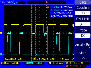
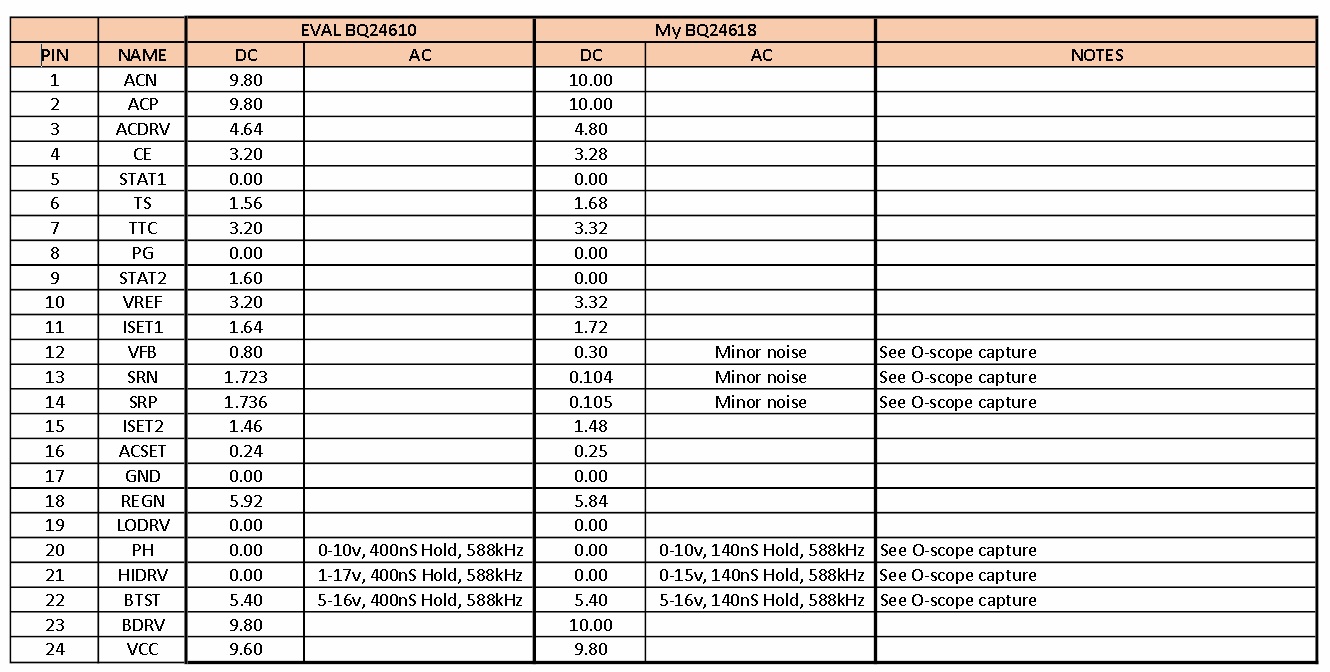
I designed and manufactured some charging boards based on the design of two Evaluation Boards I bought with the 24610 chip.

I'm charging 11, 4.2 (max voltage) Li-Ion batteries in parallel (11P).  I adjusted the  various resisters to set the charge voltage for 4.2, the battery current (precharge and termination) to 1.6A and AC supply limit to 1.32A.

I had to adjust the precharge current because the 30 minute timer would time out when charging a deeply discharged pack.  Hence the 1.6A battery precharge current (I authored that other post...).

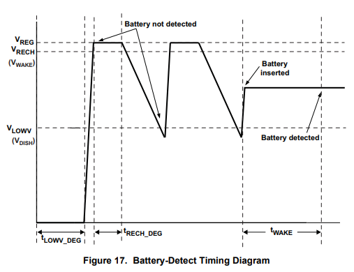
Anyway, when the battery pack is below 3.1V, the Evaluation board is in Phase-1 and charges the pack with 1.6A...and this happens no matter what the battery pack starting voltage is.

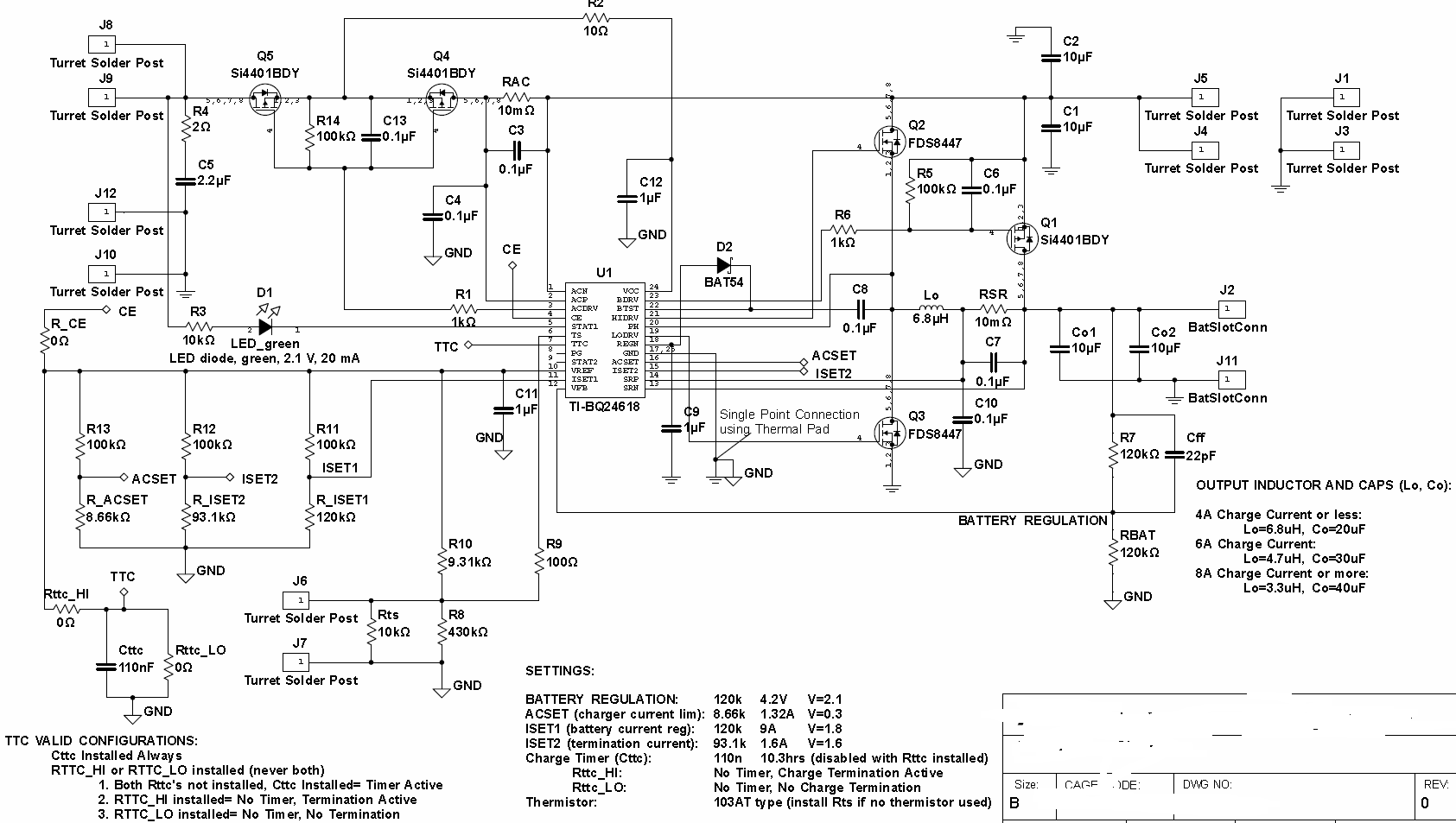
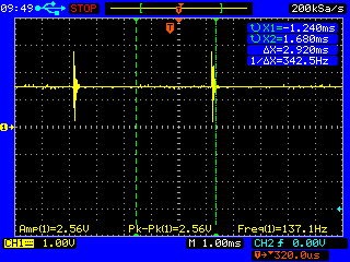
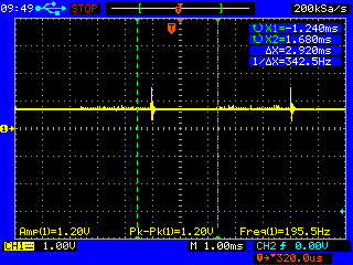
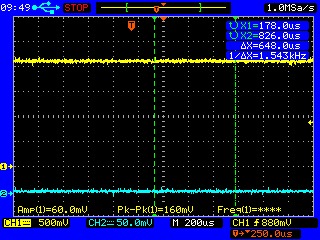
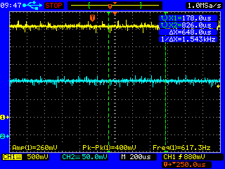
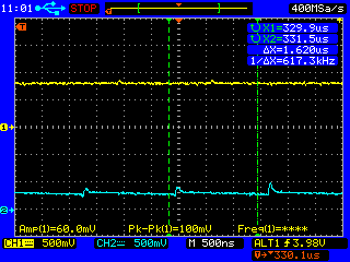
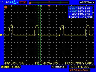
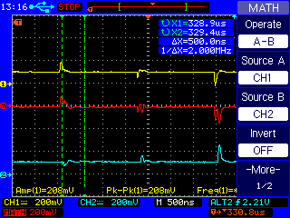
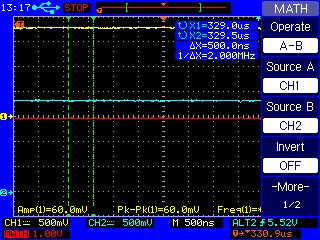
With my design (pretty much copied from the EVAL schematic), my charger behaves same as the evaluation board....except that if the starting voltage of the pack is below 2.25V, the charger will behave oddly.  The charging current varies between 10mA and 100mA, the HIDRV gate seems like it's switching...but looks sinusoidal and noisy...and the LODRV is at 0V.  Almost as if some sort of fault is starting and stopping it...

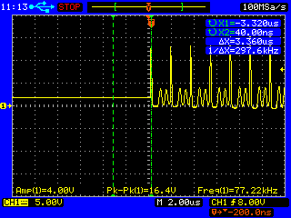
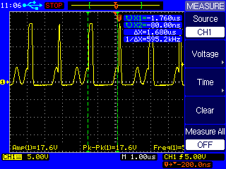
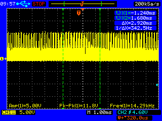
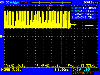
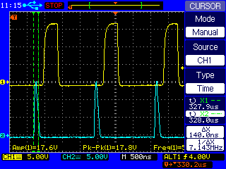
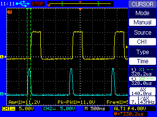
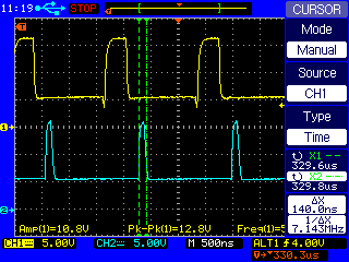
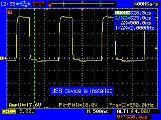
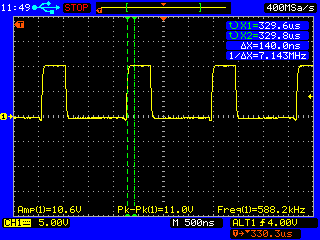
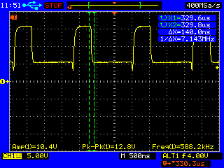
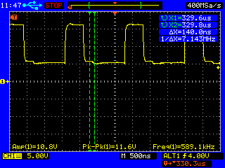
When the pack eventually reaches about 2.25V, then the thing kicks off into Phase-1, the pack charges at 1.6A and the drive signals on the HIDRV and LOWDRV gates look normal (square waves about 600kHz...not 50% duty cycle though...as should be).  And it charges to 3.1V where it kicks into Phase-3 CV mode as it should....but then instead of terminating the charge at 1.6A, it charges all the way down to a battery pack draw of less than 100mA....

I'm thinking I could have a damaged inductor or LODRV MOSFET...but before I start replacing components...I thought you might have some insight.

I would have though if I blew something....that everything would be inoperable or flaky.  In my case, it's only a problem with precharge phase (but only when pack is less than 2.25V) and current termination.

Might be the design (which is pretty much copied from EVAL schematic) or a blown part...but which?  Or other?

Again, the EVAL boards don't seem to care what about the 11P pack's starting voltage...and they stop charging at about 1.6A battery draw.  Yes, the EVAL boards are reconfigured to match this design.

Tom

  •  More info.  Attached is the Gate of the high drive MOSFET when the battery voltage is below 2.5v (or very low) and when above.  When above, all appears to operate normally.

    I replaced the LOW drive MOSFET, and it's the same.  Makes sense, since I'd think no parts are defective since it charges in all three phases fine...except when battery voltage is low....and it doesn't stop at the programmed stop current of 1.6 amps at the end of Phase-3.

    But it appears to actually read the 1.6A Phase-1 charge current and Phase-3 termination current correctly, because in Phase-1 when the batter voltage is between 2.25 and 3.1, it correctly regulates to 1.6A.  Very odd.

    Note that also, when this odd thing is happening, it appears the gate drive signal is on and off.  As for my ISET charging LED, it's ON...and sometimes blinks.  But again, when the battery voltage goes high enough, everything works fine (except for termination current not terminating at 1.6A).

    Tom

  • The last signal with the pair of square waves is the gate signals going to the high and low drive MOSFETs. Yellow is the low drive.

    In the single plots, the signal shows in the gate of the high drive when battery pack voltage is low (below 2.2 volts). Two captures. The low drive MOSFET appears to just be 0v.
  • Hello Thomas,
    Just as a sanity check, what voltage do you measure on the TTC pin of your board, during deeply discharged battery and near termination?
  • Hi.

    Unfortunately, I'm away this week and can't make that measurement. However, I will say that the thermistors are not attached to the battery pack. They are in air. Therefore, if your thought was thermistor, it should not make the signals better as battery voltage increases (and heats) because they are measuring air. And they are not defective likely, because it happens on both boards I am testing...and the same lot of thermistors is also attached the same way to the EVAL boards and they behave fine.

    Tom
  • Hi,

    I made some measurements while the battery pack was a very low voltage.  Around 1.3V.  Measurements were made with an o-scope, in case there was noise embedded:

    The positive supply to the battery pack was at 1.3, but had a noise spike on it, probably from the bad signals going to the high drive MOSFET.

    The VFB, therefore, had a similar profile:

    The TTC pin was solid with no noise at 3.28V.

    The TS pin was solid with no noise at 1.6V.

    The ACP and ACN pins were also noiseless, and measured about 10V (which is AC supply voltage).  I didn't write those voltages down, but I think that's what it was.  Anyway, they were at a DC level and appeared fine.

    The SRP and SRN signals were also noiseless and at 1.52V (probably slightly different, but not measurable on the o-scope).

    REGN was noiseless at 5.8V.

    That's where "things appear good" end.

    PH is sometimes 1.6V and flat, and sometimes very noisy:

    Same with BTST.  Periodically 5.68V, and periodically noisy:

    Keep in mind, things magically work fine once battery voltage level (11P pack) finally reaches 2.0V-2.5V

    Any idea?

    v/r

    Tom

  • Thoughts:

    I suppose I should point out that my EVAL boards have the 24610 chips, but my design is using the 24618 chips. Could there be a difference given a deeply discharged 11P pack?

    Also, could this have something to do with the battery detection part of the process? Could it be because there are so many batteries in parallel that the 24618 chip is detecting some sort of error condition...until the pack gets to a higher voltage...then things appear more normal? Again, the 24610 EVAL board doesn't do this.

    Lastly, looking at the ...18 datasheet, REGN or VREF LDOs overloaded or "not at correct levels" will stop charging. Could they be overloaded or not at "correct level"?

    Tom
  • Ok, how about this?

    In the ...618 datasheet, it talks about the charger operating in "nonsynchronous" mode when the battery voltage is lower than 2 volts. This seems to fit my situation, as I'm seeing different charge characteristics when the battery voltage is lower than (about) 2V.

    The datasheet talks about a bootstrap capacitor (section 8.3.11) being involved in the MOSFET switching, as well as the Pin Functions section talking about a bootstrap cap of 0.1uF between PH and BTST.

    The EVAL board schematic does not have this capacitor. The datasheet's Figure 19 "Typical System Schematic" also does not have this capacitor. Therefore, neither does my design.

    So although the EVAL board works properly when the battery voltage is below 2V...and does not appear to have this bootstrap cap, could this be the source of my issue? Perhaps the EVAL boards are working...sort of by accident because the ...610 chip is slightly different and able to handle it?

    The datasheet implies this bootstrap cap is required for nonsynchronous operation...but none of the TI schematics have it...nor does the EVAL boards. So is it required for battery voltages below 2V?

    Thoughts?
    Tom
  • Hello Thomas,
    You do have a bootstrap capacitor in your schematic at C8, otherwise you would not be able to drive the high-side FET at all. Can you include a scope capture of the battery voltage when you are below 2.2V? Please include Battery voltage and charge current in the scope capture. Can you also check if your battery pack has undervoltage lockout and what voltage level it is tripped at?
  • Hi,

    The August 20 post above has an O-scope capture of the battery voltage when the pack is below 2.2V. See above. I'll get a capture of the current also, but in addition to the battery voltage, I posted captures of some of the other signals.

    The battery pack does not have a low voltage lockout. It's just an 11P LG 1NR18650-MJ1 Li-Ion pack. And keep in mind, I have two evaluation boards and two of my boards. My boards use the ...618 chip, the EVALs use the ...610 chip. The EVAL boards work just fine with the pack below 2V. So there is a difference...when the objective was for there to be no difference. Objective was to copy the EVAL design but use the ...18 chip in case we needed to charge off of USB.

    The boards appear to work perfectly fine....except if the pack is initially very discharged....but the EVAL boards handle it just fine....where my boards do not.

    The datasheets talk about the chip forcing operating into nonsynchronous mode when the battery is below 2V...or when average SRP-SRN voltage is below 1.25mV. Although the threshold for good and bad operation is not 2V...but "around" 2V (2.1-2.3), it might be related to this mode or not. But I'm suspicious of it.

    Again, I have EVAL boards that work fine...

    Tom
  • Hi Thomas,

     If possible can you show us a zoomed in capture of the pulses of VBAT. We are looking to see if the voltage is similar to the battery absent detection in 

  • Hi,

    I have the measurement you wanted and additional info.

    Both of my boards do the same thing, and I think it is related to the mode when the charger is forced into "nonsynchronous mode" that the datasheet talks about in Section 8.3.11.  Although the transition voltage is a little different between the two boards, they both behave the same.  Below 2 volts (one board is 2.9, the other 2.16), instead of a Phase-1 precharge current of 1.6A, it only charges at 0.016A.  Exactly 100x less (-40dB).  Maybe this is just a coincidence, but I think that is telling us something.  Above 2 volts, it charges fine.

    And there is a transition that the charger goes through for about 10 seconds or so when it changes from 16mA charge current to 1600mA charge current.

    Below is the battery voltage and current when the battery is charging at 16mA.  CH1 yellow is the voltage, and CH2 blue is the current (100mV/A probe).  As you can see, voltage and current are steady, and it's charging...but only at 16mA (I also have a very accurate in-line current meter, so the O-scope is just to see if there is any high-frequency switching going on...which there is during the "transition".  So below is low battery voltage and the charger charging a 1/100th the programmed PHase-1 current:

    And when the voltage gets to a "trip point" voltage, there the charger goes through some soft of "transition", I'll call it.  This lasts for about 10 seconds or so.  Two plots below, two different time scales (a zoom in):

    You can see it is trying to set the current to 1600mA at a period of about 3mS or so.

    Then after about 10 seconds of that...what I'll call a "transition", the current locks in to 1600mA, like it is supposed to do:

    So I'll say that when the charger is in synchronous mode, it charges with the correct precharge programmed current of 1600mA, but when the battery voltage is low and it is in nonsynchronous mode (presumed), it only charges at 16mA.

    Thoughts Please?  This is telling, I'm sure.  Any other measurements I should make?

    Tom

  • Correction to the first paragraph: One board 2.0V and the other is 2.16. 2.9V was a typo.
  • The thread has been quite for a while. It is considered solved and closed. Thanks!
  • It is not resolved, as can be seen from the lack of response from TI.  I have put it on the Back Burner but will continue investigations next week.  I will compare the input of each pin of the 24618 on my board to each pin of the EVAL board that has the 610 chip.  I may not find any differences...and if that's the case, I will swap out my 618 chip for the 610 chip and see if the 618 chip, being designed for USB, actually behaves differently when in non-synchronous mode....

  • Hi, I ran a comparison test between the TI EVAL board and my PCB in the non-synchronous mode (11P battery pack below 2V) and in synchronous mode (battery pack between 2.5V and 2.7V).

    In synchronous mode, the PCB charges the pack with 1.6A (Const Curr mode) fine, but for ending the constant voltage mode, the PCB does not stop at the programmed termination current of 1.6A.  It keeps going.

    As for non-synchronous mode, when the battery pack is very discharged (below 2V), the following table of measurements was made, comparing the EVAL board to by PCB:

    Eval-PCB Comparison.xlsx

    Eval-PCB Comparison.pdf

    Things look the same except for SRP and SRN...which is expected because the battery charge current is 0.02 or so.  The other differences are some minor noise on the VFB/SRN/SRP lines.  The below is an o-scope capture of both the EVAL board VFB (yellow) and the PCB VFB (blue).  There is some switching noise...but nothing that I believe should send the charger into oblivion.  The SRN and SRP have similar noise ripples:

    Another difference is HIDRV, PH and BTST lines.  Again is a comparison, with the TI-EVAL board being yellow:

    HIDRV:

    PH:

    BTST:

    LODRV signals are at ground for both boards.

    So with the above signals, the EVAL board is correctly charging the pack with 1.6A, while my PCB is struggling to get to 20mA.

    Now, when the battery pack is above 2 to 2.2 volts or so, both the EVAL board and my PCB charge correctly....except for the LODRV signal:

    EVAL board LODRV:

    PCB board LODRV:

    You can see that although my PCB is charging with 1.6A, the LODRV signal seems to be inverted from the EVAL board LODRV.  ???

    These are the other signals from the EVAL board:

    HIDRV:

    PH:

    BTST:

    And these are the same three signals from my PCB:

    HIDRV:

    PH:

    BTST:

    So there is a lot of info, here...any leads you can give me as to why the charger can't charge a pack that has fallen below 2V?

    Any insight you can provide will be appreciated....

  • Also, I put two probes on the SRP and SRN lines, and used the o-scope math function to subtract them.  As you can see, it would appear that the noise glitches can instantaneously make the output current sense resister to measure 50mV to 100mV (red is the MATH function:

    Could this cause the MOSFET drive signals to instantaneously shut down?  Maybe my SRP/SRN lines are run too close to switching signals?

    The EVAL board measures this way:

    Could this be as simple as a noisy output current sense resister measurement??  Would that cause what I'm seeing???

  • Tom,

    Could you please check e2e.ti.com/.../728226 and see if it is helpful for you?

    Thanks!
    Please click "This Resolved my issue" button if this post answer your question.
  • Hi, thanks.
    I checked all my MOSFETs and they are all wired correctly, as is shown on the schematics I posted. I also checked the library parts and the physical parts on the board. All ok.

    Remember that once the charger IC goes into synchronous charging (battery voltage above 2V or so), it charges at the correct current. Also, the STAT LED is correct throughout. The issue is when the circuit is in non-sychronous mode (battery voltage below 2V) and then also termination current, which I suspect is related to the same issue.

    Unless somebody has other ideas, I'm down to only two things to try: Replace the ...610 IC on the evaluation board with the 618 chip (which is what my PCB uses) and make sure it's not the actual chip, and the second thing to try is to re-layout the board so that the SRP and SRN lines are less noisy. Those lines have more noise on them than the EVAL board due to where I routed those lines.

    Obviously re-laying out the board is extreme...and frankly, if it was the noise on those lines that was doing it...why only in non-synchronous mode? If that made sense to somebody, then I'd feel ok about re-doing the board. But it works fine once the battery voltage is above 2 volts (or so)...so I'm not really confident that the issue is the noise on the SR lines....because if that was it...why would it work fine in synchronous mode??

    Tom
  • Tom,

    1. Please double-check current sense resistor value, placement and connection.
    2. Is there gauge or protection IC in between the charger output and the battery? Or does the battery have built-in gauge/protector?
    3. Please do cross check on the EVM and your board. e.g. swap the device on your board to the EVM and see if the device works or not.

    Thanks,

    Ning.
    Please click "This Resolved my issue" button if this post answer your question.
  • Hi, thanks for the reply.

    1. I have.  It is fine.  And remember, it regulates the correct current when in synchronous mode (battery voltage above 2V).  This issue is related to non-synchronous mode, apparently...

    2. No, it's just batteries.  Also, I can put a 1-ohm reslster in place of the battery pack and re-create the anomaly.

    3.  Will do that.  Have not had a chance yet...

    v/r

    Tom

  • Hi,

    The thread has been quite for a while. It is considered solved and closed.

    Thanks!
    Please click "This Resolved my issue" button if this post answer your question.