This thread has been locked.

If you have a related question, please click the "Ask a related question" button in the top right corner. The newly created question will be automatically linked to this question.

LM3410: LM3410 USING PROBLEM

Part Number: LM3410

Hi all,

I met some problems when using LM3410 in my design.

My design parameters:

Vin=5V;

Iin=300mA;

Iled=2.5A;

Vout=6.2V

and my schematic shows as below:
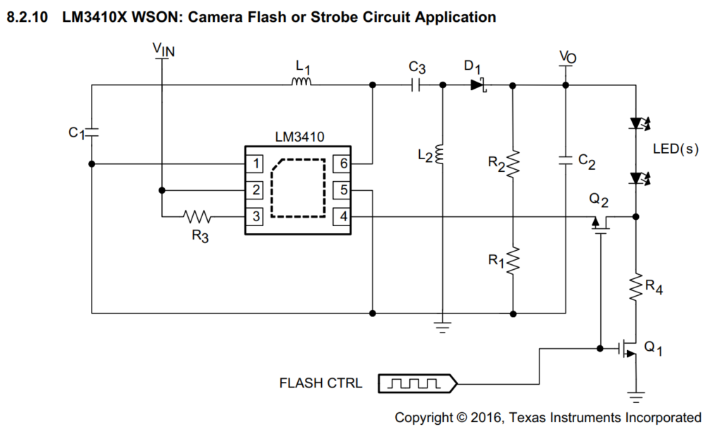
My question:

1 Should not R2 and R1 be connected to FB PIN? Is R1 1Ω or 1KΩ?

2 The LED current is designed as 1.5A,but because of the resistance of Q1, the current value should be less than Vfb/R4=1.27A,isn't it?

3 When SEPIC Converter is not necessary,can the part be deleted?

and my design as follow:

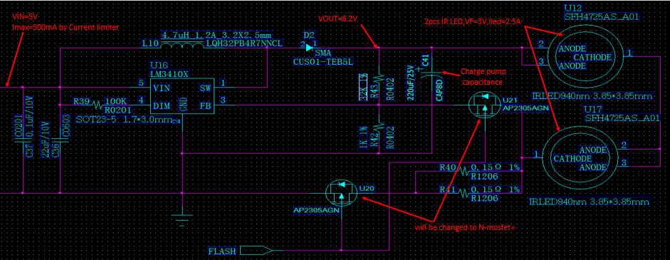
Q4:Please guide me for N-mos selection.Because of the resistance of U20,How to make sure the current of LEDs is up to 2.5A?

Q5:Please guide me for capacitance selection and Vout setting.Flash pulse width is 1ms,the energy of charge pump capacitance is 1/2*C*U*U(=0.5*C*6.2*6.2)

LED flash energy cost:2pcs*VF*Iled*T=2*3V*2.5mA*1ms=15mJ;The capacity of charge pump capacitance should not be less than 780UF(Energy loss is not considered).

Q6:Are there any other questions or suggestions?Thank you very much.

  • Hello,

    1) R1 and R2 should be connected to fb. R1 should be a 1 Kohm.
    2) Yes the Rdson of Q1 is in series with R4.
    3) If you use a boost there will be a large inrush when power is connected. You may want to put a bypass diode across L1 to charge C2.
    4) The original design used N-channel part number ZXMA3A14F, 6.5 mohm parts for Q1 and Q2. The current sense resistance including Q1 needs to be 0.205V/Rsense=2.5A, Rsense total = 0.082 ohms. If you have two 0.15 ohm resistors that equals 0.075 ohm so the MOSFET needs to be about 0.007 ohm at it's nominal operating temperature, 0.075 ohm plus 0.007 ohm = 0.082 ohm.
    5) This is the tricky part, see example below. The energy in the capacitor is (1/2)CV^2 however the LEDs cannot use most of that energy. It can draw current from the capacitor only if the voltage is high enough.

    The voltage on the capacitor needs to be able to supply almost all of the current when Q1 closes. It will discharge as current flows to the leds which means the LM3410 must add current to keep it regulating at 2.5A. If the capacitor discharges too far the LM3410 will not be able to supply all of the current. This means you need to know what the Vf of the LED is at 2.5A and at a lower current to determine the delta V of the capacitor. Note that R4 is part of the LED voltage. This will allow the calculation to figure out what the value of the capacitor needs to be.

    As an example, if Vf is 6.2V at 2.5A and 5.7V at 1.5A then the voltage start and stop points are 6.402V (6.2V + 0.205V) and 5.823V (5.7V+0.123V). A simple close approximation would be discharge at 2A (2.5A+1.5A)/2. For 1 mS the i = C * (dv/dt) would be 3,450 uF. To reduce this value resistance can be added in series with the LED stack but the voltage set-point would have to be increased. Adding resistance in series will also make it easier to pick the correct charge voltage for the LED stack since the Vf on the LED can vary a little especially with temperature.

    Best Regards,