


I took a WEBENCH design for a 10-14 Vin, 12 V / 8 A out buck/boost converter controlled by the LM5175. The output is extremely unstable without adding significantly more capacitance. The design specifies 9 x 22 uF (198 uF) capacitance. I can somewhat stabilize the output by adding another 1000 uF
Here is a snapshot of the schematic from the tool:
 Here is my re-drawn schematic used for my PCB design:

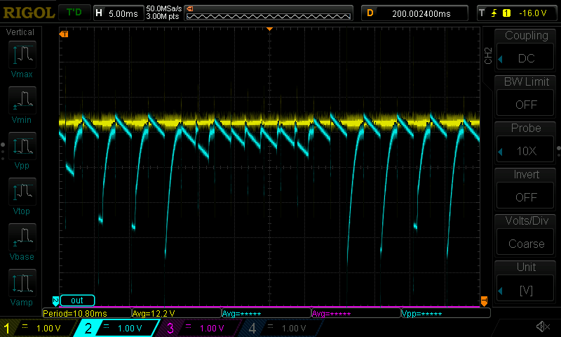
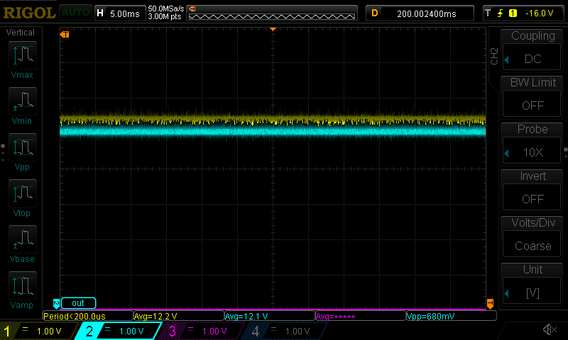
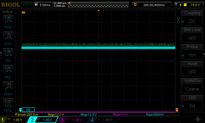
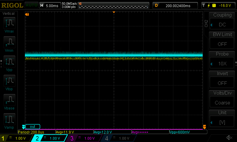
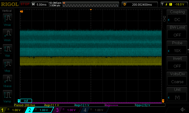
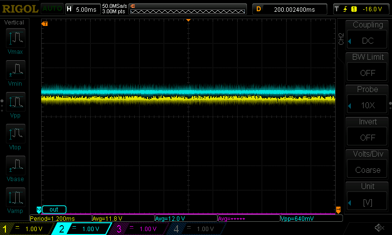
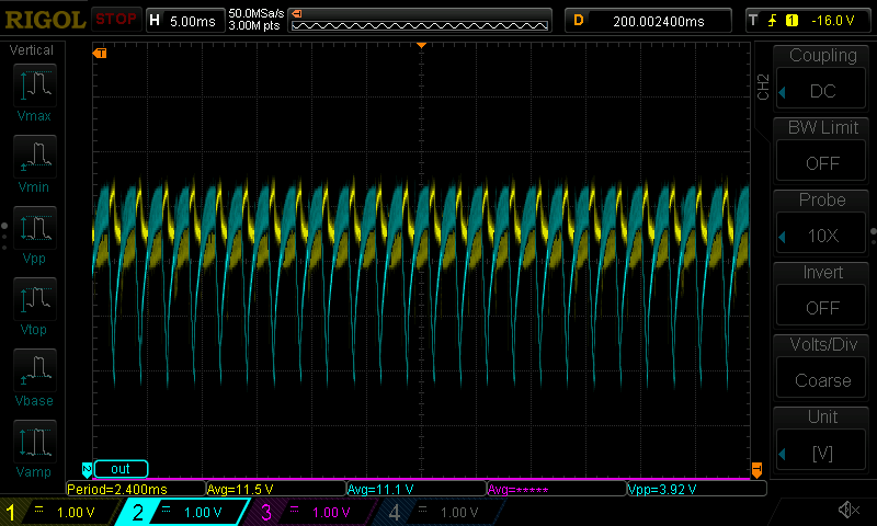
Here are scope shots showing different loads & capacitance. Yellow = input to PCB. Blue = Output from PSU:
- No additional caoacitor added. Minimal load (< 100 mA). Audible buzzing from inductor
- 1000 uF capacitor added. Minimal load ( <100 mA). No audible buzzing:
- 1000 uF capacitor added. 20 W load. No audible buzzing:
- 1000 uF capacitor added. 3.3 A load. No audible buzzing:
- 1000 uF capacitor added. 5 A load. no audible buzzing. Iitially unstable, then stabilizes:
- 1000 uF capacitor added. 6.7 A load. no audible buzzing; unstable output:
- 2200 uF capacitor added. 6.7 A load. no audible buzzing.
- Unstable. 8 A fuse input burnt out. After shorting fuse with wire, PSU smoked and failed.


I'm curious why essentially 6x'ing the output capacitance solves the problem...
- is the WEBENCH design under specified?
- Do I have a schematic problem?
- Could counterfit components used by the PCBA manufacturer be the issue?
- I have a few more copies of the board I can test on; I'm not sure where to begin probing for other issues.
- Why does the 6.7 A load cause instability for the 1000uF fix?
Thanks in advance.


