Hello,
We are using the TLV70215 and looking at the output capacitor ESR requirements.
The datasheet states the equivalent ESR should be less than 200mOhm.
We have a 10V, 1uF Multi-Layer Ceramic Capacitors (MLCC) on the output as well as a few local 100nF bypass caps around our FPGA.
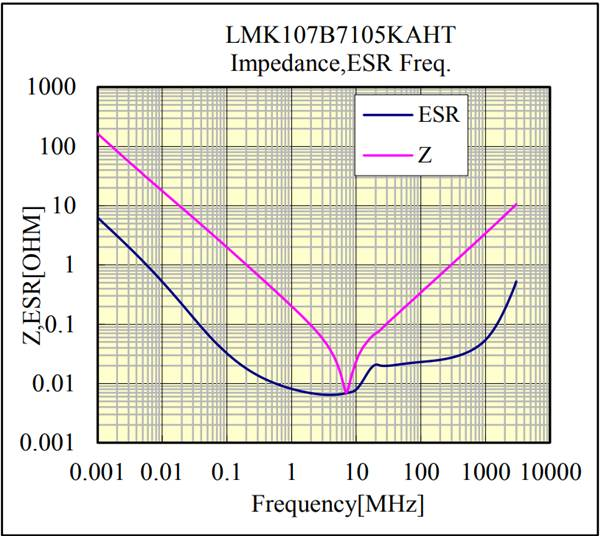
<< ESR across frequency image copied below >>
At what frequency range should we evaluate ESR from the datasheet curve?
This curve shows greater than 6 Ohms at DC & 0.7 ohms at 7MHz.
The 100nF bypass caps and they have similar ESR curves. Even if we consider them all to be in parallel, we have around 2 Ohms of effective ESR on the output caps of the regulator at DC.
Could you please let us know if this is a problem?
If so, could you recommend an output capacitor that would be better?
Thank you, Keith


