This thread has been locked.

If you have a related question, please click the "Ask a related question" button in the top right corner. The newly created question will be automatically linked to this question.

TPS7A88-Q1: Request for Schematic Review for LDOs

Part Number: TPS7A88-Q1
Other Parts Discussed in Thread: LP5912-Q1, , TPS74701-Q1

HI Team,

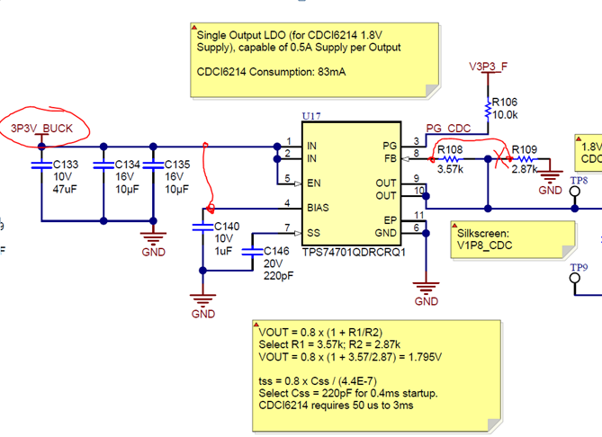
I am currently working on an automotive reference design that involves the TPS7A88-Q1 and LP5912-Q1. Before going into layout, I would like to request a schematic review to assess whether the selection of components in the schematic is optimal for the application. Current consumption estimates are also included in the schematic.

HSDC056A(001)_Sch_LDOPWR_TPS7A88Q_LP5912Q.PDF

Thanks,

Michael

  • Hi Michael,

    Channel 1 of the TPS7A88-Q1 schematic looks fine per my understanding of your application.  You have met the datasheet requirements and followed the recommendations for the resistor divider.

    Channel 2 looks okay from what I can see.  I do not see your output capacitor(s) on this channel.  Please ensure that you have at least the minimum 10 uF capacitor on the rail close to the LDO output pin.

    The LP5912-Q1 also looks okay from what I can see.  Please make sure that your output capacitor is within the output capacitance requirement.

    You may wish to consider TPS74701-Q1 in place of LP5912-Q1 as it is more flexible for the output capacitor.

    As you move to layout, keep in mind that the primary heatsink for these LDOs is the GND plane of the PCB.  Be sure to maximize the copper around the LDOs within your application constraints.  Please also keep in mind that to minimize any inductance in the feedback look, that it is best to keep the components on the same layer as the LDO.

    Very Respectfully,

    Ryan

  • Hi Ryan,

    Per your suggestion, I updated my schematic for TPS74701-Q1. Could you do a quick review to check on the connections? I noticed that this device seems not to require a feed-forward capacitor like some other LDOs.

    **Update Jan. 22 2019**

    After receiving boards back, the following schematic issues were observed. 

    1. BIAS pin did not have VIN connected to it (I mistakenly thought this was a reference bias output from the chip, which I see with some other regulators.)
    2. Feedback network was not connected correctly.

    To prevent others in the community from experiencing the same issue, please note the following schematic errors found and connect according to the marked locations:

    Thanks,

    Michael

  • Hi Michael,

    Your updated schematic is correct with the provided notes of your intended use case.

    While TPS74701-Q1 does not require a Cff, you may still use one if you wish. The following Application Report goes into some detail of things to consider if you choose to use a Cff:

    www.ti.com/.../sbva042.pdf

    Very Respectfully,
    Ryan