This thread has been locked.

If you have a related question, please click the "Ask a related question" button in the top right corner. The newly created question will be automatically linked to this question.

LM5025A: start up several times before it becomes stable

Part Number: LM5025A
Other Parts Discussed in Thread: LM5025

Hi,

my customer is using LM5025A in a DC/DC converter.

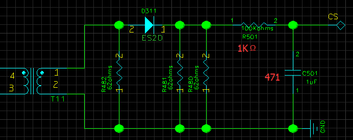
Input range: 80-200VDC.  output: 14V 71.5A. switching frequency 100kHz. deadtime=300ns. Transformer ratio 12:3.

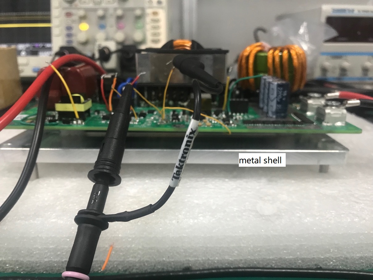
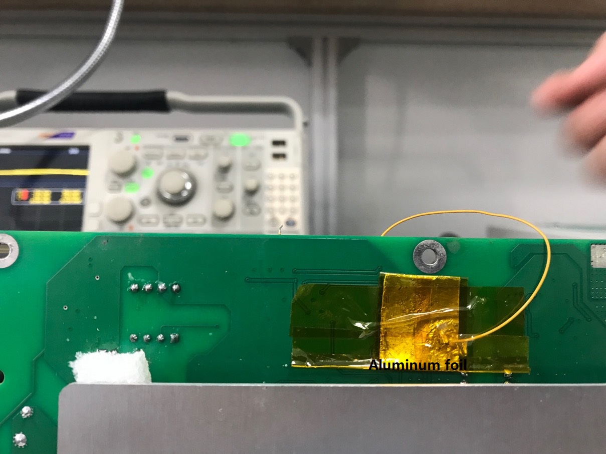
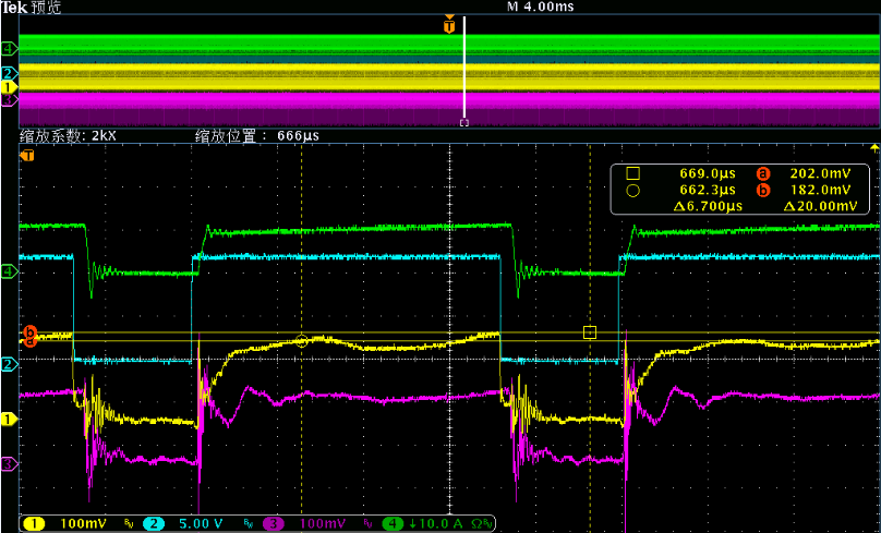
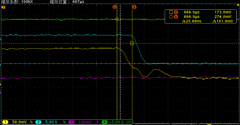
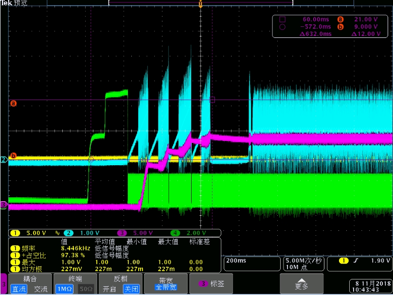
During start up, the waveform is as below:

purple- Output voltage,  green- RAMP,  blue- COMP.

It can be seen that the device has restart several times during the start-up.

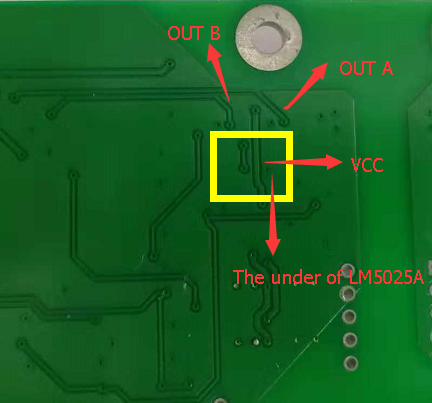
The schematic is as below.

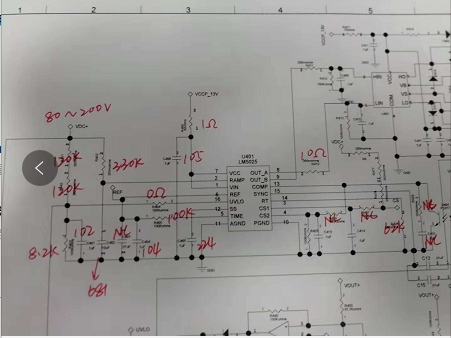
What may cause the restart and how to make improvement?

  • Hi Howard,

    I would check the Vcc rail, I suspect it may be dropping below the UVLO level during start-up.

    Regards

    Peter
  • Hi Howard,

    Any update on this issue?

    Thanks

    Peter
  • Peter,

    The previous problem is solved and it's their own power supply issue.

    But now they've got some other issue.

    1. Output voltage will decrease as long as the output current rises. The output voltage should be set to 13.8V.

    Output current(A)

    Output voltage(V)

    0

    13.89

    2.7

    13.84

    13

    13.46

    25

    13.07

    40

    12.6

    2. There will be audible noise after the circuit has operated for a while.

    3. The output voltage will be 13.1V when the load is 1Ohm. When they put the board on metal shell (picture shown below), the voltage will drop to 12.1V.

    If we add aluminum foil at the back side of LM5025A, the problem is solved.

    could you please tell what could be the reason for such strange phenomenon and how to improve?

    And there are two other questions about the device itself:

    4. Can SYNC pin be floating? what's the difference between floating and grounded?

    5. Do we have a paper to specifically describe how COMP and RAMP generate the PWM signal? There is a simple block diagram on the datasheet, but it's not clear for the customer to know how the PWM is generated.

  • Hi Howard,

    I think the output voltage dropping as the load increases is related to the audible noise, please check if the control loop is going unstable and the duty cycle is varying and causing an audible noise issue.

    The large aluminum plate is acting like a capacitor plate and coupling noise into the controller. They could put a ground plane in the PCB under the controller to achieve the same solution at the small aluminum shield.

    The LM5025 reference design on the product page shows SYNC connected to GND when unused.

    The LM5025 is a voltage mode controller and uses a ramp signal compared to the error sign to generate the PWM gate drive, it is described in section 7.3.9 of the datasheet. See extract below.

    An external resistor (RFF) and capacitor (CFF) connected to VIN and GND are required to create the PWM ramp
    signal. The slope of the signal at the RAMP pin varies in proportion to the input line voltage. This varying slope
    provides line feedforward information necessary to improve line transient response with voltage mode control.
    The RAMP signal is compared to the error signal at the COMP pin by the pulse width modulator comparator to
    control the duty cycle of the main switch output. The Volt Second Clamp comparator also monitors the RAMP pin
    and if the ramp amplitude exceeds 2.5 V the present cycle is terminated. The ramp signal is reset to GND at the
    end of each cycle by either the internal clock or the Volt Second comparator, which ever occurs first.

    Regards

    Peter

  • Hi Peter 

    I am user of the controller LM5025A and the problems mentioned above are the problems I encountered in the process of using the controller.

    Now I have solved the problem of noise, the reason of which is that the transformer has  mechanical vibration caused by no leaching,but i have no found how is caused the voltage drop as long as current goes up.

    You suggested that put a ground plane in the PCB under the controller to instead the small aluminum shield,here are the PCB images.

    Please help to analyze whether there is any problem in the routing of this PCB.

    Thank you !

    Rui Wang

  • Hi Rui,

    If the addition of the aluminum shield solves the drop in the output voltage as current increases then I would the areas.

    1. does the PWM gate starts to oscillate
    2. Is the current sense signal picking up noise and starting to trip the current limit internally
    3. is the feedback loop signal, COMP and RAMP changing as load is incresed
    4. if you increase Vin does vout increase at full load, is the design operating at max duty cycle?

    What net did you connect the aluminum plate to?

    Regards

    Peter
  • Hi Peter,

    I have solved the problems that i meet before,now i have a new question that CS1 sampled signal is abnormal,The details are as follows:

    The RC cut-off frequency is 338KHZ,and switching frequency is 100KHZ.

    I  measured the waveforms at both ends of R480 and C501 respectively,as follows:

    yellow is both end of C501,blue is PWM OUT A,purple is both end of R480,green is primary  side current of the transformer.

    You can find that yellow drops before purple with green and follows the blue,the subtle yellow is about 25ns faster than blue.

    Why does this happen and Whether or not depends on the mechanism inside the controller.

  • Hi Howard,

    CS1 has leading edge blanking which will pull the CS1 pin to 0V internally to discharge the pin at the end of every cycle and this may happen before the PWM out goes low due to delays within the IC. The CS1 pin is then help low for the first 50ns of the next pulse to blank any leading edge spike on the CS signal.

    When making such measurements I suggest that you also ensure the correct calibration of the scope probes and compare them on the same high frequency signal source to ensure the response in matched.

    Regards

    Peter