This thread has been locked.

If you have a related question, please click the "Ask a related question" button in the top right corner. The newly created question will be automatically linked to this question.

LM8364: Issue with low voltage detection

Part Number: LM8364
Other Parts Discussed in Thread: TL431, LM431, TPS3701

Hello,

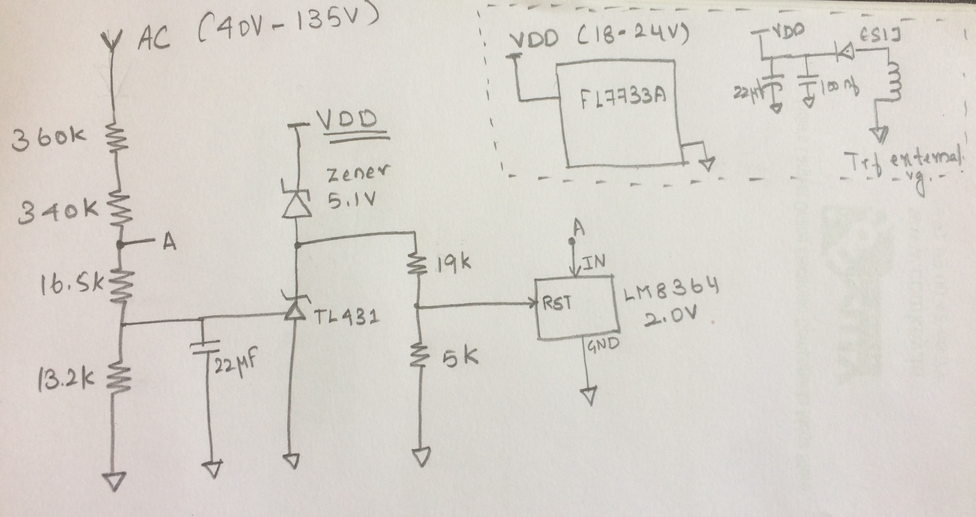
We are using LM8364 in a LED driver for AC line under voltage protection, we are trying to pull down the driver IC's supply pin with LM8364's reset pin.

But, we are facing trouble because it is not pulling down the driver IC's supply before Vdet. ( we are getting 0V at reset pin, but no sinking)

Can you please tell if this IC can be used for such application?

Regards

Sen

  • Hi Sen,

    Can you give us a schematic or more details on how the LM8364 is connected to the driver IC?

    -Marcoo
  • Hello Marcoo,

    I have attached the schematics here. The AC input is after a rectifier diode (40V to 135V)

    We are using TL431 for line over voltage detection and it works fine in this application, LM8364's Vdet is at 50V line input.

    We are using 19K and 5K because reset line maximum voltage is till 6V, also i tried setting the sink current at 1mA.

    Please let me know if you need more clarity.

    Regards

    Sen

  • Hi Sen,

    I believe the issue can stem from multiple sides.
    1. The LM8364 does not have enough current to conduct properly.
    2. The Zener does not have enough current to regulate and pull VDD down if reset is low. 20V/19k = 1mA of current and that might not be enough to make it conduct properly.

    Try scaling the 19k/5k resistors to conduct more current. Try the UV with the TL431 cathode disconnected to see if the TL431 also affects the circuit under UV.

    I am not a fan of having 2 different solutions for the same output. I would be more comfortable if you implemented a solution like figure 21 on the LM431 datasheet. In this solution the zener would conduct through an NPN and the UV and OV will be working together.
    www.ti.com/.../lm431.pdf

    -Marcoo
  • Hello Marcoo,

    Thank you for you help, that application should work well for us. Althought i have a doubt on the capacitor charge and discharge path, can you help me how to design that?

    Regards
    Sen
  • Hi Sen,

    The capacitor/diode/resistor combination is not necessary. Also the output is inverse of what you need so you need to add an additional NPN to create the inverse logic.

    I thought more about this and have created a simpler solution with the TPS3701. I believe using the TPS3701, the solution can be more simple. See the attached tina as a schematic example. 3264.Noname.TSC

    -Marcoo

  • Hello Marcoo,

    The solution with LM431 with an additional NPN works fine for us. Appreciate your support, thank you.